Supercharge Your Innovation With Domain-Expert AI Agents!

Building reinforcement and insulation

a technology for building reinforcement and insulation, applied in the direction of walls, construction, covering/linings, etc., can solve the problems of increasing the possibility of disproportionate building collapse, disproportionate collapse of one corner of the tower block, and partial collapse of the building

Active Publication Date: 2022-07-12
EDSCER WILLIAM GEORGE
View PDF13 Cites 0 Cited by
  • Summary
  • Abstract
  • Description
  • Claims
  • Application Information

AI Technical Summary

Benefits of technology

[0009]securing to the metal framework the EWI panels to clad the building and enhance the thermal insulation of the building.
[0028]The insertion of a single tie bar as described above into each tie bar anchorage hole establishes a secure anchorage of the wall panels to the floor / ceiling panels of the building, but does not materially affect the bending resistance of the floor / ceiling panels. Particularly when the floor / ceiling panels are hollow precast panels with internal voids, it may be desirable as part of the method of the invention to strengthen the panels around the peripheral outer wall of the building to protect against disproportionate collapse of the building caused by bending distortion of those hollow panels. This may be achieved by placing alongside but spaced from each tie bar within the internal voids of the hollow floor / ceiling panels one or more reinforcing bars which are then surrounded by the grouting compound in the second stage of the method of the invention when that grouting compound is injected into floor / ceiling panel voids which provide the tie bar anchorage holes. The reinforcing bars may be supported by spacer elements at least some of which are mounted on the tie bars, and the cage of reinforcing bars and spacer elements should be sized to permit its insertion into the internal voids of the hollow floor / ceiling panels through the core holes drilled from the outside of the building. The connections between the reinforcing bars and spacer elements should be secure connections such as screw threads, grub screws or welded joints. The spacer element located at the innermost end of the tie bar is the anchorage referred to in claim 1 herein and is securely attached to the tie bar by threading or similar other secure means. However all of the spacer elements have an anchorage function in addition to supporting and positioning the reinforcing bars, in that they contribute to the secure bonding of the grout to the concrete internal walls which define the voids in the hollow floor / ceiling panels. They act to restrict the grout flow to ensure that the grout consolidates and backs up against those concrete internal walls and by doing so ensures that the internal voids in the floor / ceiling panels are completely filled with grout for the entire length of the tie bars and anchorage bars. The total encapsulation of all of the spacer elements by the high strength grout ensures that the spacer elements cannot move and become a composite part of the tie bar anchorage construction, capable of resisting any reasonable specified load). The reinforcing bars are preferably made from distressed deformed steel reinforcing bar stock, as are the tie bars, to secure a good bond with the grouting compound after it sets. Alternatively, they may be completely threaded, for example using Gripbar® stock as manufactured by Stainless UK Ltd, enabling them to be screw-threaded to all of the spacer elements as well as providing a good bond to the grouting compound.

Problems solved by technology

One well documented collapse of such a large panel system high rise building in the United Kingdom was the partial collapse of the Ronan Point tower block in 1968, when an internal gas explosion blew out part of an external wall, leading to the disproportionate collapse of one corner of the tower block.
It is understood that the partial collapse of the building became disproportionate in part because the outer walls and many of the floor / ceiling slabs immediately above the explosion were no longer supported by the external wall blown out by the explosion, and in part because the weight of falling masonry brought down the outer walls and many floor / ceiling slabs of the storeys immediately beneath the damaged load-bearing external wall.
Therefore, hanging EWI panels on the outside of a large panel building increases the possibility of disproportionate collapse of the building if an external large panel wall should be damaged.
This increased possibility of disproportionate collapse is at its greatest when the EWI panels are heavy panels, such as precast concrete EWI panels, but still exists even when the EWI panels are lightweight panels such as those based on the use of mineral wool which has a nil fire rating.

Method used


Image

  • Building reinforcement and insulation
  • Building reinforcement and insulation
  • Building reinforcement and insulation

Examples


Embodiment Construction

[0053]Embodiments of the present invention will now be described by way of example only and with reference to the accompanying drawings.

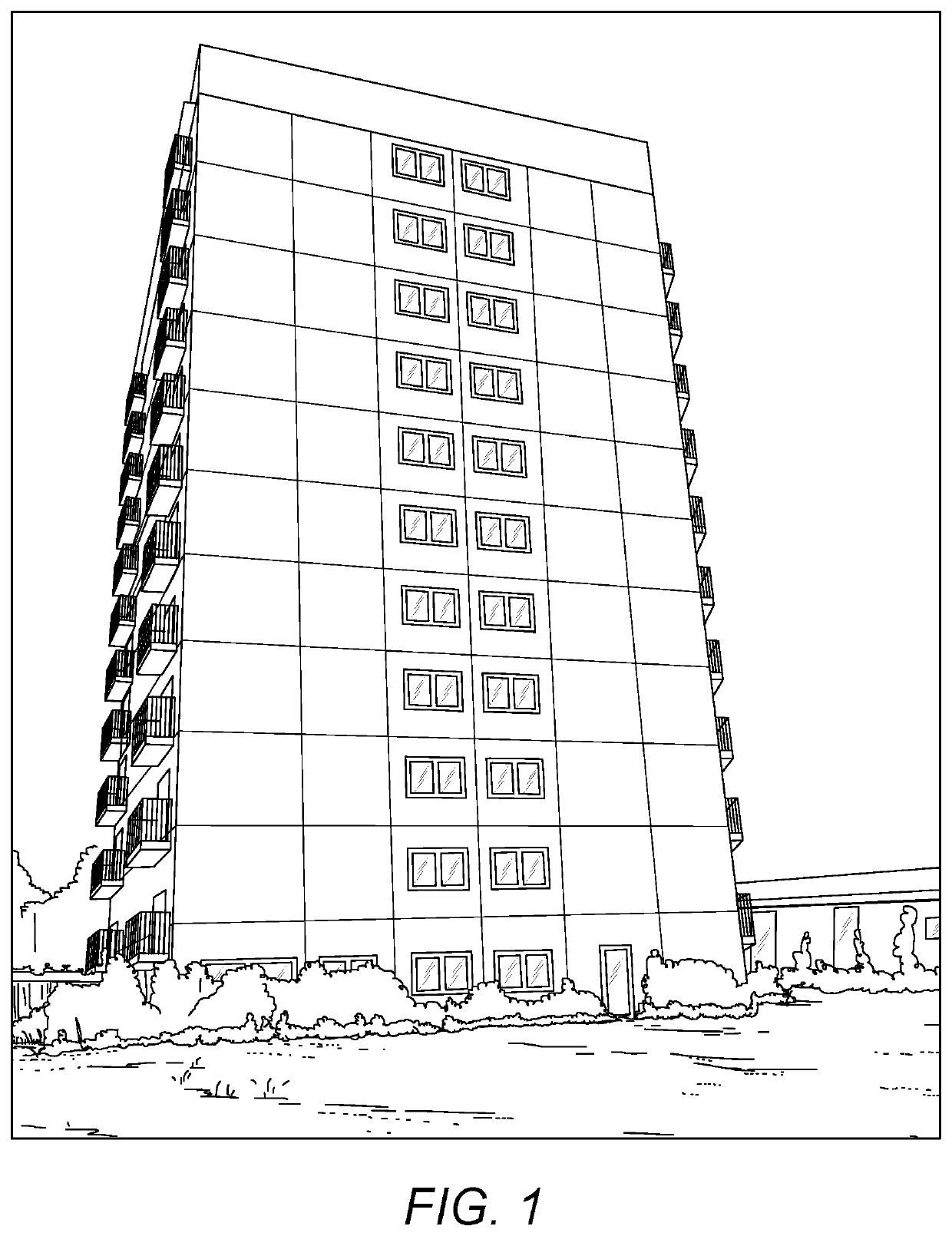
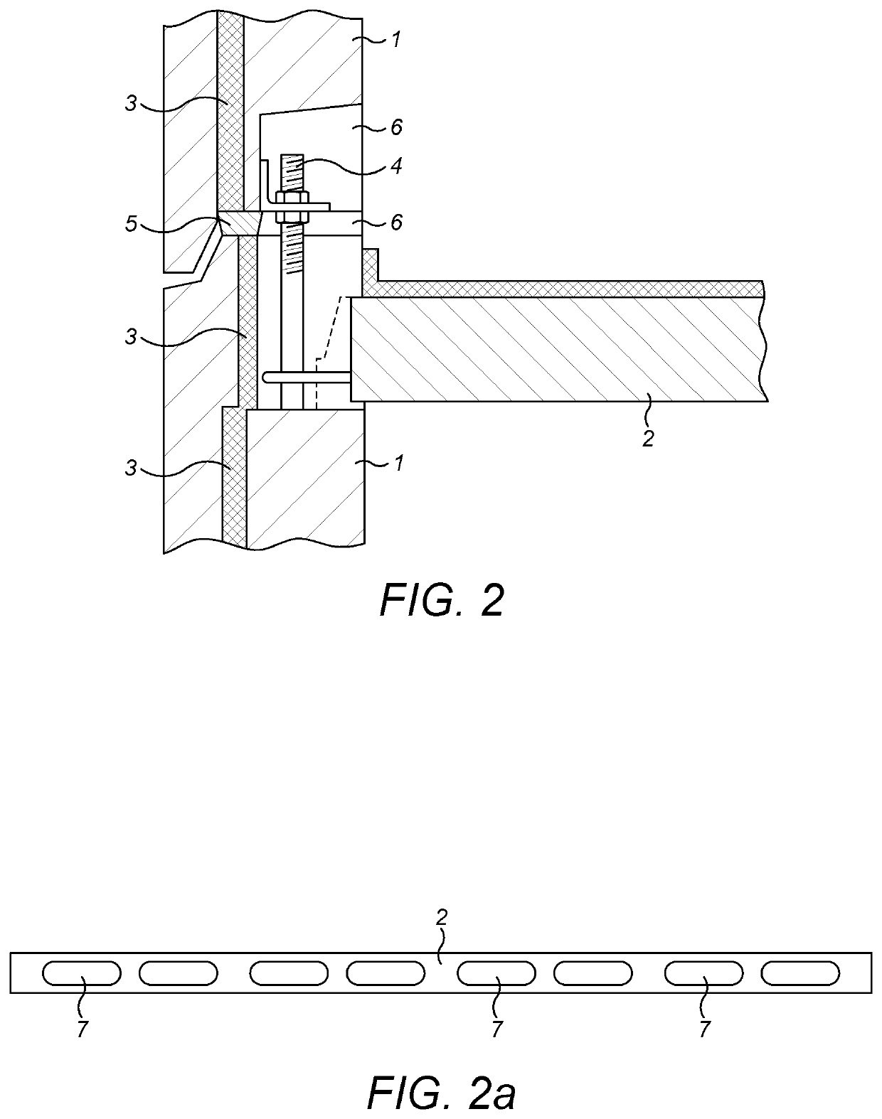
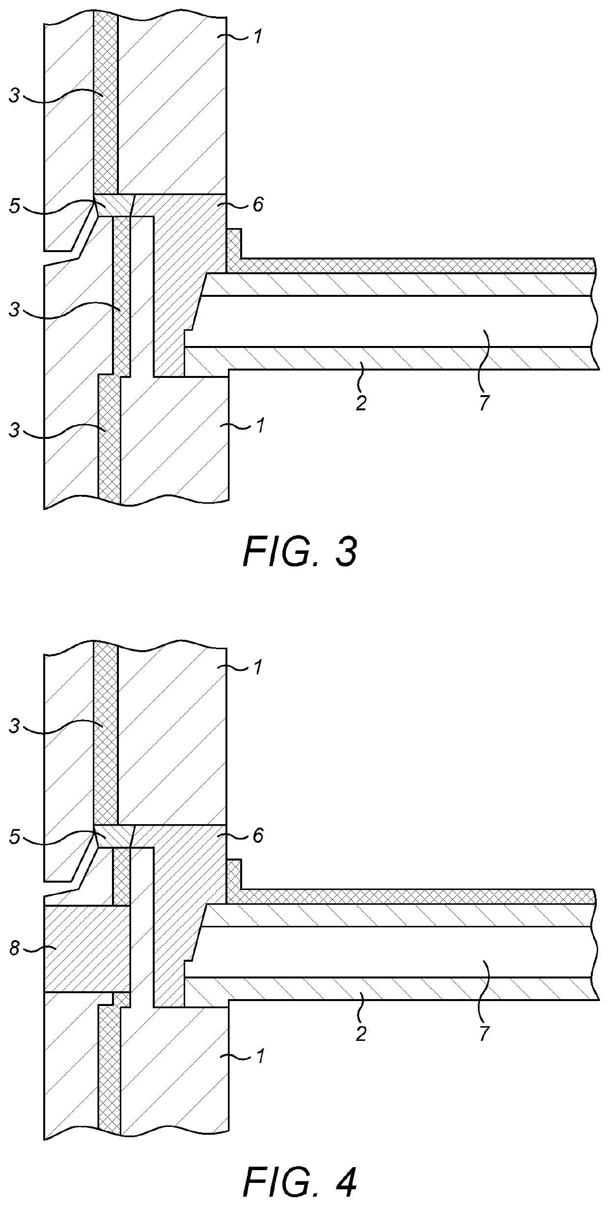
[0054]Referring first to FIG. 1, there is shown a tower block building to be clad and reinforced against disproportionate collapse according to the method of the invention. The building is of large panel construction, and FIGS. 2 and 3 show how the external wall panels 1 and floor / ceiling panels 2 of the building are bolted edge to edge in the large panel construction method. The wall panels 1 include internal thermal insulation layers shown schematically as 3, which separate each external wall panel 1 into inner and outer leaves. It is the inner leaf which is load-bearing, in that it supports the adjacent floor / ceiling panel 2. The floor / ceiling panels 2 rest on top edges of the external wall panels 1 with an array of bolts 4 connecting the inner leaf of each external wall panel 1 both to the inner leaf of the wall panel 1 immediately above and to ...


PUM


Abstract

A method is provided for securing external wall insulation (EWI) panels to the outer walls of a high rise building of large panel construction. The method involves first identifying the location of internal voids in outermost floor / ceiling panels of the building; and then creating continuous passages through the outer load-bearing wall panels of the building into the located internal voids, with each such passage forming a tie bar anchorage hole extending into the adjacent floor / ceiling panel. Down the length of each tie bar anchorage hole is inserted a tie bar that has, at an inner end portion, an anchorage, and at an outer end portion, an externally screw-threaded portion that projects from the outer load-bearing wall panel. A pattress plate is located at the outer end of each anchorage hole, with the externally screw-threaded outer end portion of each tie bar extending through the associated pattress plate.

Description

FIELD OF THE INVENTION[0001]The invention relates to a method of reinforcing and insulating a certain class of existing high rise modular building. The buildings to be reinforced and insulated in this way are all concrete frame buildings, but the method is most advantageously applied to large panel system buildings. These are systems in which load-bearing precast concrete wall slabs are erected edge to edge and topped with precast concrete floor / ceiling slabs which are secured edge to edge to the tops of the load-bearing wall slabs. Each floor / ceiling slab forms part of the ceiling of the storey defined by the interconnected wall slabs and part of the floor of the next higher storey of the building. One well documented collapse of such a large panel system high rise building in the United Kingdom was the partial collapse of the Ronan Point tower block in 1968, when an internal gas explosion blew out part of an external wall, leading to the disproportionate collapse of one corner of ...

Claims


Application Information

Patent Timeline
Patent Type & Authority Patents(United States)
IPC IPC(8): E04B2/94E04B1/04E04B1/21E04F13/08
CPCE04B2/94E04B1/043E04B1/215E04F13/08E04G23/0218E04G23/0296E04B1/04E04G23/02E04B1/21E04B2/88
Inventor EDSCER, WILLIAM GEORGEJONES, JOHN
Owner EDSCER WILLIAM GEORGE
Features
  • R&D
  • Intellectual Property
  • Life Sciences
  • Materials
  • Tech Scout
  • Unparalleled Data Quality
  • Higher Quality Content
  • 60% Fewer Hallucinations
Learn More