Fastening device

a technology of fastening device and electronic tablet, which is applied in the direction of traveling carriers, travelling articles, other accessories, etc., can solve the problems of electronic tablet, difficult to grip, and difficult to grip, and achieve the effect of reducing the weight of the electronic tablet during the session of us

Active Publication Date: 2022-07-12
BRUN
View PDF14 Cites 0 Cited by
  • Summary
  • Abstract
  • Description
  • Claims
  • Application Information

AI Technical Summary

Benefits of technology

[0017]Compared to already existing devices, the invention has at least one of the following advantages: a device in accordance with the invention is relatively simple to produce, is easy to apply by a user, is robust in use, is comfortable, and is discreet. In some embodiments, the self-adhesive can be detachable and sometimes repositionable by pulling on an edge, an angle, of the self-adhesive which, however, resists detachment during use thanks to the way according to which the connector is disposed having the effect that a traction force is distributed homogeneously.

Problems solved by technology

However, gripping an electronic tablet can prove to be difficult, delicate for at least one of the following reasons.
First, an electronic tablet, even if it is relatively light, has a considerable weight to support during a session of use.
In addition, the session of use can be relatively long, which may accentuate a feeling of discomfort.
An electronic tablet can be difficult to hold; the electronic tablet can easily slide.
However, in this case, the weight of the electronic tablet creates a large moment which can generate muscle tension, especially in the long run.
However, it is then difficult to keep the electronic tablet in balance, in particular when the other hand acts on the electronic tablet, for example, by pressing on the keys which are displayed on a touch screen.
Added to this is that the user can get tense by not wanting to drop the electronic tablet which represents a relatively expensive and fragile object, and which, in addition, generally contains a lot of personal and precious data.

Method used


Image

  • Fastening device
  • Fastening device
  • Fastening device

Examples


Embodiment Construction

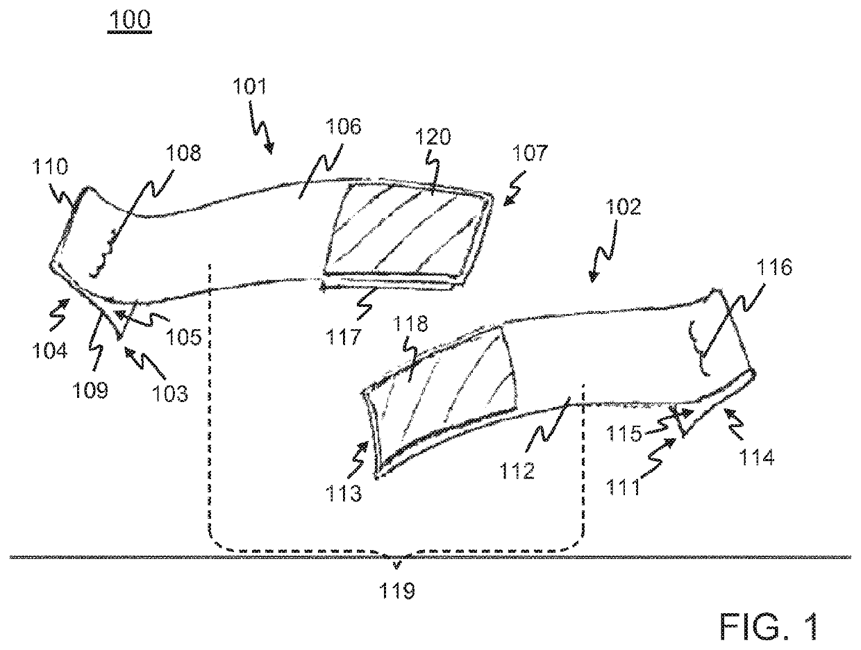
[0034]FIG. 1 schematically illustrates a gripping device 100 in a state decoupled into two portions. FIG. 1 shows a schematic perspective view of the gripping device 100. The gripping device 100 can be used for an easy and ergonomic gripping of an object, in particular of a portable apparatus such as an electronic tablet. This use will be described in the following.

[0035]The gripping device 100 comprises two fastening devices 101, 102 which are decoupled from each other in FIG. 1. One of the two fastening devices 101, 102 will be designated left fastening device 101 in what follows for convenience reasons. The other fastening device will be designated right fastening device 102.

[0036]The left fastening device 101 comprises a self-adhesive 103. The self-adhesive portion 103 has a self-adhesive surface 104 and a connecting surface 105 which is located opposite the self-adhesive surface 104. A flexible strip 106 extends freely from the connecting surface 105 of the self-adhesive 103. C...


PUM


Abstract

A fastening device includes a self-adhesive part having a self-adhesive surface and a connecting surface which is situated on the opposite side from the self-adhesive surface. A flexible strip extends from the connecting surface of the self-adhesive part. The flexible strip is joined to the self-adhesive part by means of a connecting element disposed in a region on the connecting surface. This region faces a central region of the self-adhesive surface. Thus, a traction force exerted on the flexible strip is distributed substantially uniformly over the self-adhesive surface.

Description

CROSS-REFERENCE TO RELATED APPLICATION(S)[0001]This is a National Stage Entry into the United States Patent and Trademark Office from International Patent Application No. PCT / EP2018 / 072465, having an international filing date of Aug. 20, 2018, which claims priority to French Patent Application No. FR1760497, filed on Nov. 8, 2017, and to European Patent Application No. EP17306082.3, filed on Aug. 20, 2017, the entire contents of all of which are incorporated herein by reference.FIELD OF THE INVENTION[0002]An aspect of the invention relates to a fastening device. This device can be used, for example, to fasten an object on a surface of another object. Other aspects of the invention relate to a gripping device and a case for an electronic apparatus.DESCRIPTION OF RELATED ART[0003]An electronic tablet can be used in many contexts of everyday life. For example, an electronic tablet can be used for strolling, in professional or commercial activities, for example in salons, in restaurants...

Claims


Application Information

Patent Timeline
Patent Type & Authority Patents(United States)
IPC IPC(8): A45F5/10F16M13/04A45C13/30A45F3/14A45F5/00
CPCF16M13/04A45C13/30A45F2003/142A45F2005/008A45F2200/0516A45F2200/0525A45C2011/003A45C2013/303F16M13/005
Inventor BRUN, EMMANUEL
Owner BRUN
Why Eureka
Try Eureka