Lens holder for holding a lens in a headlamp

a technology for holding a lens and a headlamp, which is applied in the direction of vehicle components, signalling/lighting devices, lighting and heating apparatus, etc., can solve the problems of reducing the light intensity transmitted by the lens, hysteretic shift, and more complex dependencies, and achieves greater robustness to temperature influences.

Active Publication Date: 2022-07-12
HELLA KG HUECK & CO
View PDF17 Cites 0 Cited by
  • Summary
  • Abstract
  • Description
  • Claims
  • Application Information

AI Technical Summary

Benefits of technology

[0008]It is therefore an object of the present invention to overcome the above-described disadvantages of prior art headlamps, and therefore to propose an improvement of a headlamp whose functionality has greater robustness to temperature influences, i.e. its light cone projected onto the roadway is not subject to any shifting and / or tilting when the operating and / or ambient temperature of the headlamp changes.
[0010]The invention is based here on the concept of creating a thermomechanical decoupling of the receptacle section and the mounting section in the design in that the thermomechanical distortion arising between the two sections is absorbed and compensated by a suitable bending of the circumferential channel between the two sections. In the event of a temperature change of the headlamp, the receptacle section of the lens holder expands or contracts to a different extent than the mounting section because the latter is fixed to the supporting frame in the plane of the screw, and the supporting frame has a different thermal expansion capability on account of the different materials. The channel according to the invention preferably has a U-shaped or arched cross-section, wherein one end section of the arch meets the mounting section and the other end section leads to the receptacle section. The channel reacts to the described unequal thermal expansion of the mounting and receptacle sections with a change in cross-section that is essentially characterized by a change in the curvature of the arch. The channel thus clearly takes on the function of a buffer, which is to say that because the two end sections of the arched cross-section each follow the thermally induced deformation of the mounting section and the receptacle section, the channel is changed in terms of its curvature and thus absorbs the transverse forces acting between the screwed-on mounting section and the receptacle section. As a result of such a thermomechanical decoupling between the mounting and receptacle sections, the lateral shear forces under the screw heads in the screw plane of the mounting section adjacent to the supporting frame caused by thermal expansion are greatly reduced so that the clamping forces transmitted by the screws are large enough to prevent irreversible deformation of the lens holder and / or supporting frame.
[0013]Preferably, the lens holder has a multiplicity of ribs, wherein the ribs are arranged on the lens holder on the outside and / or on the inside and in each case extend essentially axially along the mounting section and the transition section and the receptacle section with respect to the longitudinal axis. Such longitudinal ribs provide stiffening between the screw-attachment plane and the lens plane in order to ensure load transmission into the supporting frame and consequently adequate mechanical stability for use in vehicle operation. The longitudinal ribs in this design are dimensioned and arranged such that their presence is not accompanied by any significant bridging or stiffening of the channel according to the invention.
[0015]In an embodiment of the lens holder according to the invention, the channel can have at least a first section and a second section, wherein the first section and the second section are arranged on opposite sides of the lens holder. Under some circumstances, it may be necessary for design reasons to dispense with a channel that extends around the full circumference, and instead to provide only two opposing sections of the lens holder with a channel. In this case, the thermomechanical decoupling of the receptacle section and the mounting section accordingly does not take place in all transverse directions. With regard to the arrangement of the headlamp in a motor vehicle, preferably the upper and lower sides of the lens holder are provided with a channel so that at least a thermal-expansion-induced upward and / or downward shifting of the light cone projected onto the roadway is prevented.

Problems solved by technology

A general problem of projection headlamps is in that the different components, which usually are made of different materials, expand to different degrees on account of their material-specific coefficients of thermal expansion when changes occur in the operating and / or ambient temperature of the headlamps.
In particular, this causes a temperature-dependent shift between the light source and the lens and / or a displacement of the optical axis of the headlamp, wherein the extent of these effects usually does not change in a reversible, linear manner with the temperature, but instead more complex dependencies occur, in particular irreversible and / or hysteretic shifts and / or displacements.
Corresponding shifts and / or tilting of the light cone projected onto the roadway and / or reductions of the light intensity transmitted by the lens and / or other undesirable aberrations result from such shifts between light source and lens.
A disadvantage of this prior art device is the limitation of the shift correction to shifts between the light source and the lens along the optical axis, whereas no allowance is made for shifts and / or displacements oriented radially to the optical axis.
However, even the smallest shifts in the plane perpendicular to the vertical axis lead to a clearly visible shift in the light / dark boundary on the roadway, which can then bring about dangerous glare for oncoming traffic, for example.
After one or more temperature cycles, this causes irreversible deformations of one or both components to occur, resulting in irreversible changes in the light cone projected onto the roadway, in particular displacements of the light / dark boundary.
The same problems also arise in designs of headlamps in which the lens holder is connected to a heat sink or to another optical component.
Even when the lens holder is mounted on a component made of the same material as the lens holder, irreversible distortion of the lens holder due to temperature change can occur, since temperature gradients that can develop along the optical axis of the headlamp, in particular, lead to local differences in the amount of thermal expansion of the components of the headlamp.

Method used


Image

  • Lens holder for holding a lens in a headlamp
  • Lens holder for holding a lens in a headlamp
  • Lens holder for holding a lens in a headlamp

Examples


Embodiment Construction

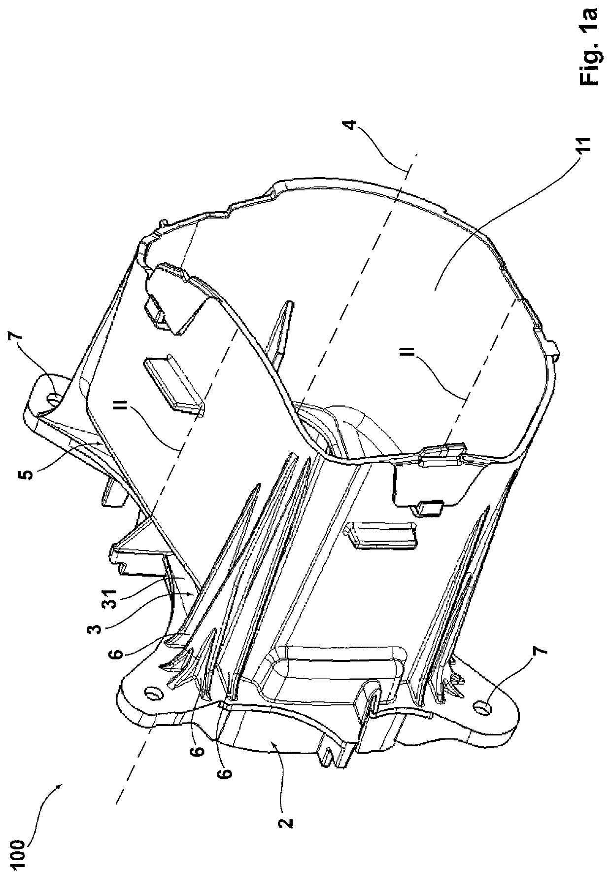
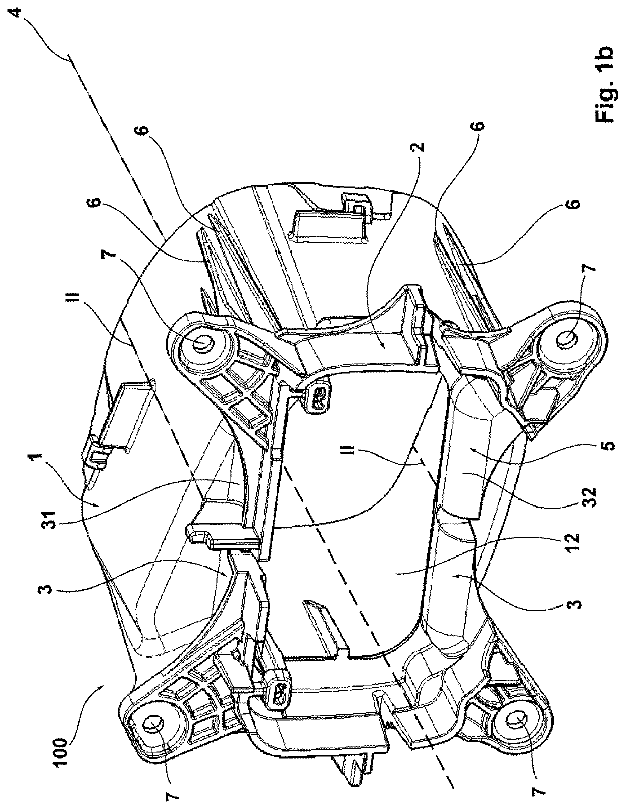
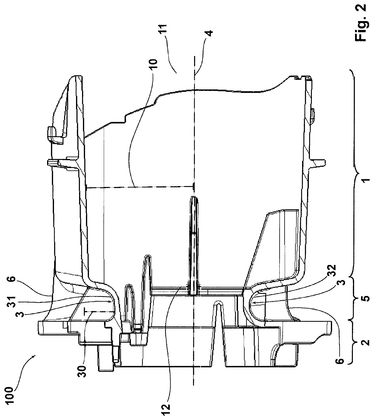
[0024]FIGS. 1a, 1b, and 2 show an advantageous embodiment of the lens holder 100 according to the invention, with a receptacle section 1, formed by a tubular hollow body, for holding a lens, with a mounting section 2 provided for connecting to the supporting frame, and with a transition section 5 that is arranged between the receptacle section 1 and the mounting section 2 and is partially surrounded by the channel 3 according to the invention. The longitudinal axis 4 passes through the geometric centroid of the lens holder 100 and forms the normal of the plane of the openings 11, 12 at the ends of the receptacle section 1. The screw openings 7 arranged on the mounting section 2 are used for the screw connection of the lens holder 100 to the supporting frame of a headlamp. The light source of the headlamp in this case is arranged relative to the lens holder 100 in such a way that the emitted light enters through the rear opening 12 of the receptacle section 1, then passes through a l...


PUM


Abstract

A lens holder for holding a lens in a headlamp, and to a headlamp having such a lens holder, wherein the lens holder comprises a receptacle section for holding the lens and a mounting section, wherein the mounting section can be mounted in the headlamp by means of fasteners. The lens holder has an at least partially circumferential channel between the receptacle section and the mounting section.

Description

[0001]This nonprovisional application is a continuation of International Application No. PCT / EP2019 / 084218, which was filed on Dec. 9, 2019, and which claims priority to German Patent Application No. 10 2018 133 061.8, which was filed in Germany on Dec. 20, 2018 and which are both herein incorporated by reference.BACKGROUND OF THE INVENTIONField of the Invention[0002]The present invention relates to a lens holder for holding a lens in a headlamp, wherein the lens holder comprises a receptacle section for holding the lens and a mounting section, wherein the mounting section can be mounted in the headlamp by means of fasteners.Description of the Background Art[0003]Headlamps for motor vehicles are sufficiently known from the prior art. Modern projection headlamps include, as essential components, a light source, in particular xenon gas-discharge lamps or light-emitting diodes (LEDs), optionally a reflector enclosing the light source at the rear, a lens arranged in front of the light s...

Claims


Application Information

Patent Timeline
Patent Type & Authority Patents(United States)
IPC IPC(8): F21S41/29F21S41/25
CPCF21S41/29F21S41/25F21S41/295
Inventor GUERRERO, DOMINGOKOERDT, CHRISTIANMEYER, ANDREAS
Owner HELLA KG HUECK & CO
Why Eureka
Try Eureka