Method for controlling power ramps with prediction in intermittent power generation plants

a power generation plant and power ramp technology, applied in adaptive control, process and machine control, instruments, etc., can solve the problems of large losses, increased cycle of said batteries, and unstable electrical systems, and achieve the effect of reducing investment costs

Active Publication Date: 2022-07-12
ACCIONA ENERGIA SA
View PDF10 Cites 0 Cited by
  • Summary
  • Abstract
  • Description
  • Claims
  • Application Information

AI Technical Summary

Benefits of technology

[0028]The present invention solves the indicated problem by means of a method for controlling power ramps with prediction in intermittent power generation plants, such as for example a photovoltaic solar plant, which avoids the battery from being completely discharged, which would prevent compliance with the maximum admissible ramp requirements given by a grid code regulation, or other similar document, in addition to minimizing the cycling of said storage systems, thereby reducing plant investment costs leading to a more rationalized use of the energy storage system, such that, in order to respect compliance with a same maximum fluctuation ramp, a minor use is made of the energy storage system.
[0030]To overcome these drawbacks, the method for controlling power ramps with prediction in intermittent power generation plants, which minimizes energy storage requirements in intermittent power generation plants, guaranteeing at all times compliance with a maximum admissible ramp value for the power being fed into the grid, PG(t), given by a grid code regulation or other similar instrument, which also improves the lifespan and the losses of the storage system of the present invention, comprises:
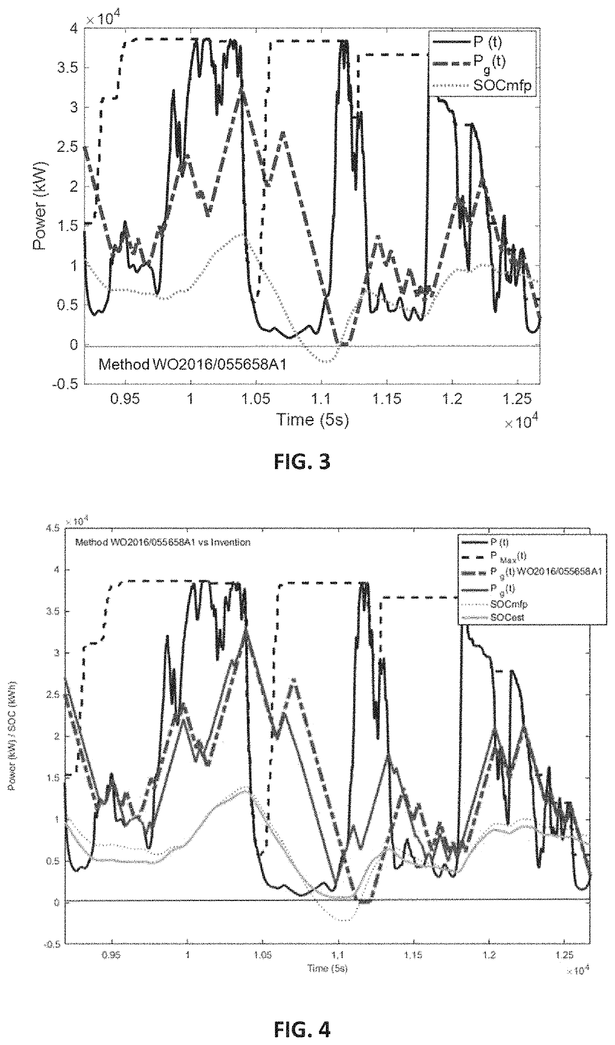
[0037]Thus, in calculating the state of charge, SOC(t), of the energy storage system according to the stabilized state of charge, SOCsta(t), the energy required by the power being fed into the grid PG(t) at said t moment in order to achieve the instantaneous power P(t) generated by the intermittent power generation plant is taken into account, whereby the battery is never completely discharged. Similarly, the battery is never fully charged in order to avoid loss of energy that is not fed into the grid.
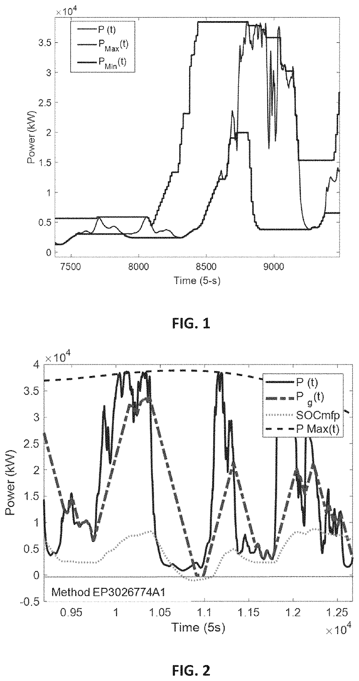
[0038]In addition, by calculating the stabilized state of charge of the energy storage system according to the state of charge required to support maximum possible fluctuation, SOCmpf(t), having calculated the maximum plant power, PMax(t), and the minimum plant power, PMin(t), in that prediction time horizon, the energy storage system is designed to support, with a very high degree of accuracy, the fluctuations that will later take place, whereby the cycling of said energy storage system is considerably reduced, increasing the lifespan thereof.
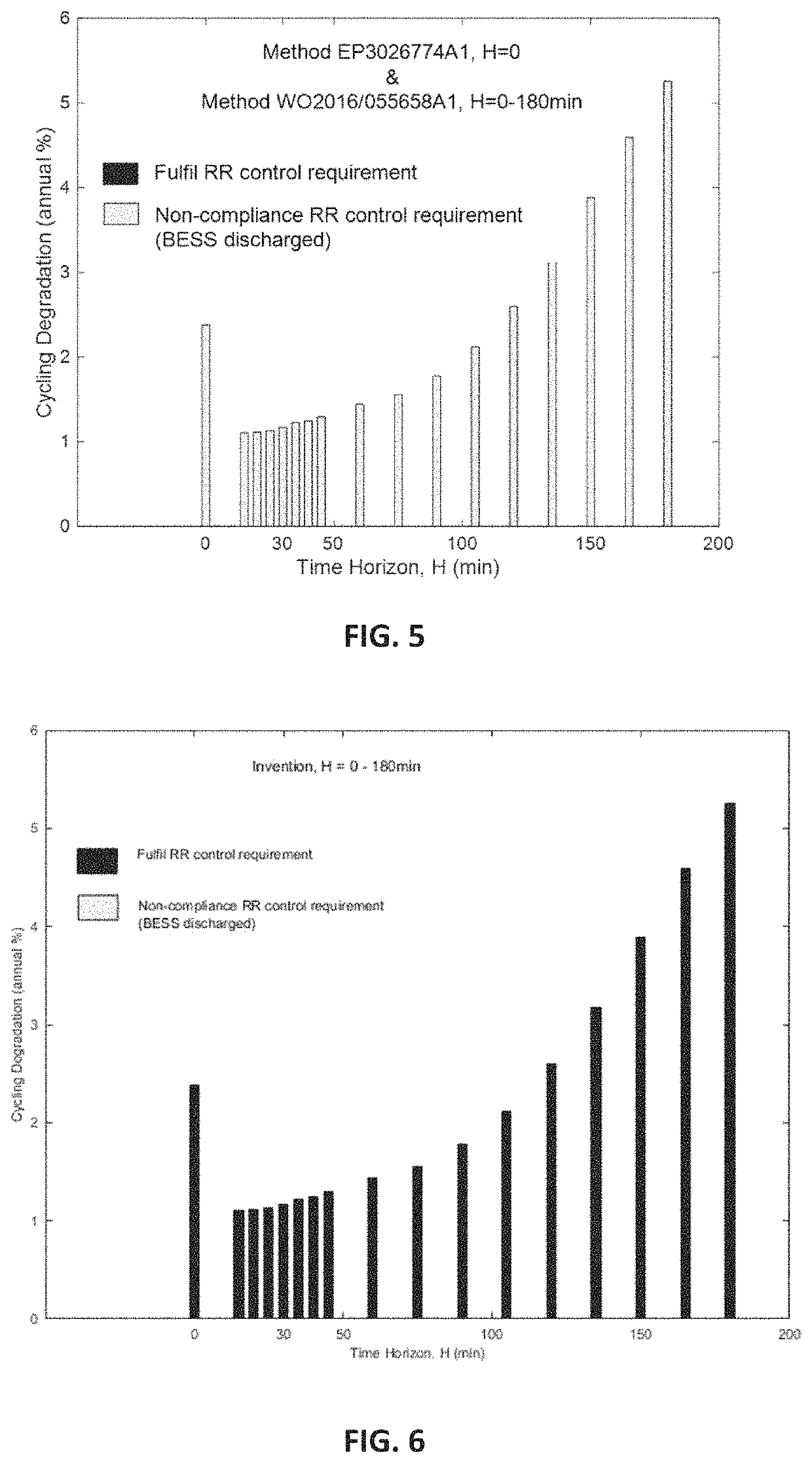
[0049]Therefore, the method of the present invention enables the BESS not to discharge completely (and hence the grid code, or other instrument, would be complied with) contrary to the methods found in European patent EP3026774A1 and International application WO02016 / 055658A1. In addition, it enables cycling degradation to be as much as 57% less that that obtained with the method found in European patent EP3026774A1, as well as a reduction of associated losses.

Problems solved by technology

Cloud cover is difficult to predict and fast in terms of its effects, so it causes fluctuations in the production of the photovoltaic plants that can cause problems in the stability of the electrical system.
Power grid operators have conducted a number of investigations on the effects of fluctuations because, since they cannot be accurately predicted at present, the grid must be equipped with sufficient control capacity to absorb them.
This requires predicting fluctuations and acting in advance by limiting the production of the plant.
Poor prediction of weather variables and the effects thereof on plant production can cause great losses in this process and may justify investment in energy storage systems.
The drawback associated to this technique is that since the sign of the power change is not known, the target state of charge SOCtar (t) of the storage system is always set at around 50%, which requires the use of a battery twice the minimum size needed to limit the maximum given ramp.
The main drawback of the method described in European patent EP3026774A1 is that, in calculating the target state of charge required for supporting the maximum possible fluctuation, the battery is prepared to support fluctuations, which in most cases do not occur, whereby the cycling of said battery increases considerably, reducing the lifespan thereof.

Method used


Image

  • Method for controlling power ramps with prediction in intermittent power generation plants
  • Method for controlling power ramps with prediction in intermittent power generation plants
  • Method for controlling power ramps with prediction in intermittent power generation plants

Examples


Embodiment Construction

[0028]The present invention solves the indicated problem by means of a method for controlling power ramps with prediction in intermittent power generation plants, such as for example a photovoltaic solar plant, which avoids the battery from being completely discharged, which would prevent compliance with the maximum admissible ramp requirements given by a grid code regulation, or other similar document, in addition to minimizing the cycling of said storage systems, thereby reducing plant investment costs leading to a more rationalized use of the energy storage system, such that, in order to respect compliance with a same maximum fluctuation ramp, a minor use is made of the energy storage system.

[0029]Any of the strategies mentioned in the background of the invention section, assess the need to modify the SOC of the storage system to support maximum fluctuation depending on the current SOC. However, if the storage system is limiting a ramp in the generated power, P(t), this power, P(...


PUM


Abstract

The present invention relates to a method for controlling power ramps with prediction in intermittent power generation plants, such as, for example, a photovoltaic solar plant, which minimizes the storage capacity required for compliance with the maximum ramp requirements for power fluctuation as well as the cycling of said storage systems, thus extending its lifespan and also reducing associated energy losses, thus reducing investment costs in the plant, such that, in order to achieve the same maximum fluctuation ramp, a minor use is made of the energy storage system.

Description

CROSS-REFERENCE TO RELATED APPLICATIONS AND PRIORITY[0001]This patent application claims priority from PCT Patent Application No. PCT / ES2017 / 070472 filed Jun. 29, 2017. This patent application is herein incorporated by reference in its entirety.OBJECT OF THE INVENTION[0002]The present invention is included in the technical field of methods for controlling power ramps with prediction in intermittent power generation plants.[0003]The object of the present invention is a method for controlling power ramps with prediction in intermittent power generation plants, such as, for example, a photovoltaic solar plant, which prevents the battery from being fully discharged, which would prevent the maximum admissible ramp requirements given by a grid code regulation, or other similar instrument, from being complied with, in addition to minimizing the cycling of said storage systems thereby reducing investment costs in the plant by carrying out a more rationalized use of the energy storage system...

Claims


Application Information

Patent Timeline
Patent Type & Authority Patents(United States)
IPC IPC(8): H02J3/38G05B13/04H02J3/32H02J7/00
CPCH02J3/381G05B13/048H02J3/32H02J7/0048H02J2203/20H02J2300/24H02J2300/28H02J3/004Y04S10/50Y04S40/20Y02E40/70Y02E60/00
Inventor GUELBENZU MICHELENA, EUGENIOPADROS RAZQUIN, ASUNROJO OCHOA, RAQUELMARROYO PALOMO, LUISMARCOS ALVAREZ, JAVIERDE LA PARRA LAITA, INIGOGARCIA SOLANO, MIGUEL
Owner ACCIONA ENERGIA SA
Why Eureka
Try Eureka