
Electric heater apparatus for electric vehicle and method of controlling same

a technology for electric vehicles and heaters, applied in vehicle heating/cooling devices, ohmic-resistance heating, transportation and packaging, etc., can solve the problems of increasing power consumption, small controllable section, high heat value in a low duty, etc., to increase the width of the inside temperature control section, enhance comfort in the indoor environment, and reduce the minimum temperature control range

Active Publication Date: 2019-12-10
HANON SYST
View PDF33 Cites 0 Cited by
  • Summary
  • Abstract
  • Description
  • Claims
  • Application Information

AI Technical Summary

Benefits of technology

The present invention is an electric heater apparatus and control method that expands the range of temperature control by expanding the width of the temperature control section and minimizing the cycling of the PTC heater. This helps to lower the minimum temperature control range, enhance comfort in the indoor environment, and reduce unnecessary power consumption and ripple current. Additionally, the invention reduces the number of cycling events and the wear and tear on high-voltage batteries.

Problems solved by technology

However measures to heat the inside of the vehicles are urgently needed because the electric vehicle, which is operated only by a motor, is markedly lower in heat value of the coolant for cooling the motor than general vehicles or hybrid vehicles using a combustion engine.
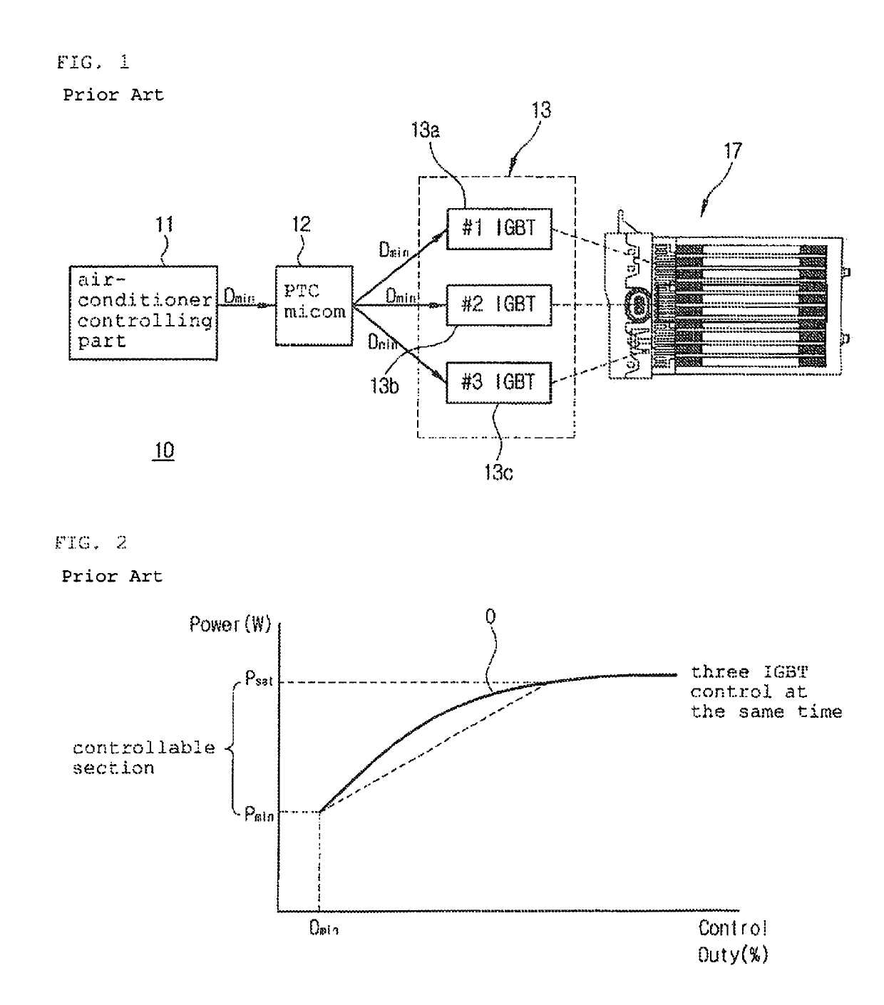
However, it has a problem in that just one duty control section is formed because the plural IGBTs are controlled at the same time, and hence, the heat value is high in a low duty and a controllable section becomes small.
So, a width of the minimum heat value becomes small, and hence, in the case that heat for temperature lower than the minimum heat value Is needed, a cycling of repeatedly carrying out ON / OFF actions at the minimum control temperature is frequently generated and it increases power consumption.
The reason of an increase of power consumption is that a large current flows by a low resistance when the PTC heater is operated at the minimum temperature.
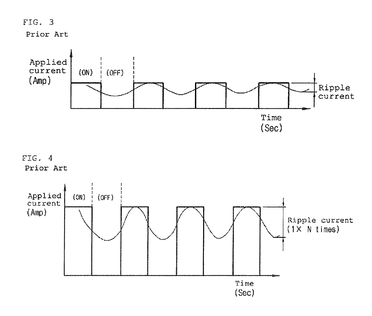
As shown in FIGS. 3 and 4, the ripple current of one IGBT is small, but when the IGBTs of the n-tuple are controlled at the same time as in the prior art, ripple current becomes N times, such that the lifespan of the battery is deteriorated.

Method used


Image

  • Electric heater apparatus for electric vehicle and method of controlling same
  • Electric heater apparatus for electric vehicle and method of controlling same
  • Electric heater apparatus for electric vehicle and method of controlling same

Examples


Embodiment Construction

[0045]Description will now be made in detail of preferred embodiment of the present invention with reference to the attached drawings.

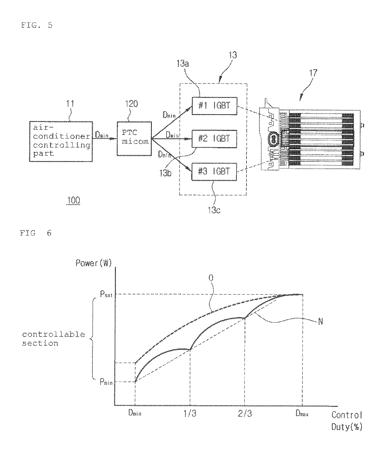
[0046]FIG. 5 is a schematic diagram of a PTC (Positive Temperature Coefficient heater) heater apparatus 100 of an electric heater apparatus for an electric vehicle according to the present invention, and FIG. 6 is a graph showing a duty control for controlling temperature in the PTC heater apparatus 100 of FIG. 5 by a divided duty control section.

[0047]In FIG. 5, components serving the same functions as the components of FIG. 1 have the same reference numerals as FIG. 1.

[0048]As shown in FIG. 5, the PTC heater apparatus 100 includes: a power supply part, (not shown) mounted in the electric vehicle; an air-conditioner controlling part 11 for controlling heating, cooling and air-blowing inside the electric vehicle; a PTC mi com 120 for controlling duty control sections of a high-voltage switching part 13, which supplies electric power to the PTC heater ...


PUM


Abstract

The present invention relates to an electric heater apparatus including a switch control part for controlling a switching part according to a control command of an air-conditioner controlling part; the switching part switched according to a switching control signal of the switch control part for supplying electric power of the power supply part from a heating part; and the heating part for receiving the electric power of the switching part and generating heat, wherein the switching part includes a plurality of switching modules set to control an output load of the heating part, and the switch control part operates one or more switching modules in serial order according to a target heating temperature.

Description

[0001]This application claims priority under 35 U.S.C. § 119 from Korean Patent Application No. 10-2011-0081036 filed Aug. 16, 2011 and Korean Patent Application No. 10-2012-0082179 filed Jul. 27, 2012, each of which is incorporated herein by reference in its entirety for all purposes.BACKROUND OF THE INVENTION[0002]Field of the Invention[0003]The present invention relates to an electric heater apparatus for an electric vehicle and a method of controlling the same, and more particularly, to an electric heater apparatus for an electric vehicle and a method of controlling the same, which can expand a temperature control width by a duty ratio (hereinafter, called ‘duty’) when operation of a PTC heater (Positive Temperature Coefficient heater) is controlled, and provide a uniform distribution of temperature increment.[0004]Background Art[0005]In general, a conventional heating system for a vehicle heats the inside of the vehicle through the steps of making a heat exchange medium (engine...

Claims


Application Information

Patent Timeline
Patent Type & Authority Patents(United States)
IPC IPC(8): B60L1/02B60H1/22H05B1/02
CPCB60H1/2218H05B1/0236H05B2203/02H05B2203/023B60H2001/2265
Inventor WON, SEUNGSIKLEE, JUNGKICHO, JUNGWONBAEK, YOUNGKEE
Owner HANON SYST
Learn More