Crankshaft driven flywheel magneto generator with circular winding for power supply in handheld batteryless combustion engines

a flywheel magneto generator and circular winding technology, which is applied in the ignition of engines, dynamo-electric machines, electrical apparatus, etc., can solve the problems of increasing the cost of winding all windings on each individual leg, affecting the effective cooling of windings during use, and requiring more tim

Active Publication Date: 2022-07-19
SEM AB
View PDF13 Cites 0 Cited by
  • Summary
  • Abstract
  • Description
  • Claims
  • Application Information

AI Technical Summary

Benefits of technology

[0010]The power producing coil is simply wound on a cylindrical bobbin forming one single one-phase winding that may be produced rapidly and without any indexation of the bobbin during winding. The stationary circular power coil could be wound on the bobbin and assembled into the generator structure by clamping the two claws together. No iron core with legs needs to be present during winding which further simplifies the winding process, avoiding any transitions from one leg to another leg during winding and thus eliminating weak points in the windings from one leg to another.
[0014]This set-up of the inventive magneto ignition system for battery less hand-held combustion engines obtains all necessary power from the stationary circular power coil winding for driving both the ignition power supply as well as the ignition timing module. The single stationary circular power coil winding requires less space and is much easier to produce with less weak points in the coil windings.

Problems solved by technology

This may hinder effective cooling of the windings during use.
Producing a flywheel magneto system using cylindrical windings oriented in a star shape on legs directed radially, involves more time and hence increase costs for winding all windings on each individual leg.

Method used


Image

  • Crankshaft driven flywheel magneto generator with circular winding for power supply in handheld batteryless combustion engines
  • Crankshaft driven flywheel magneto generator with circular winding for power supply in handheld batteryless combustion engines
  • Crankshaft driven flywheel magneto generator with circular winding for power supply in handheld batteryless combustion engines

Examples


Embodiment Construction

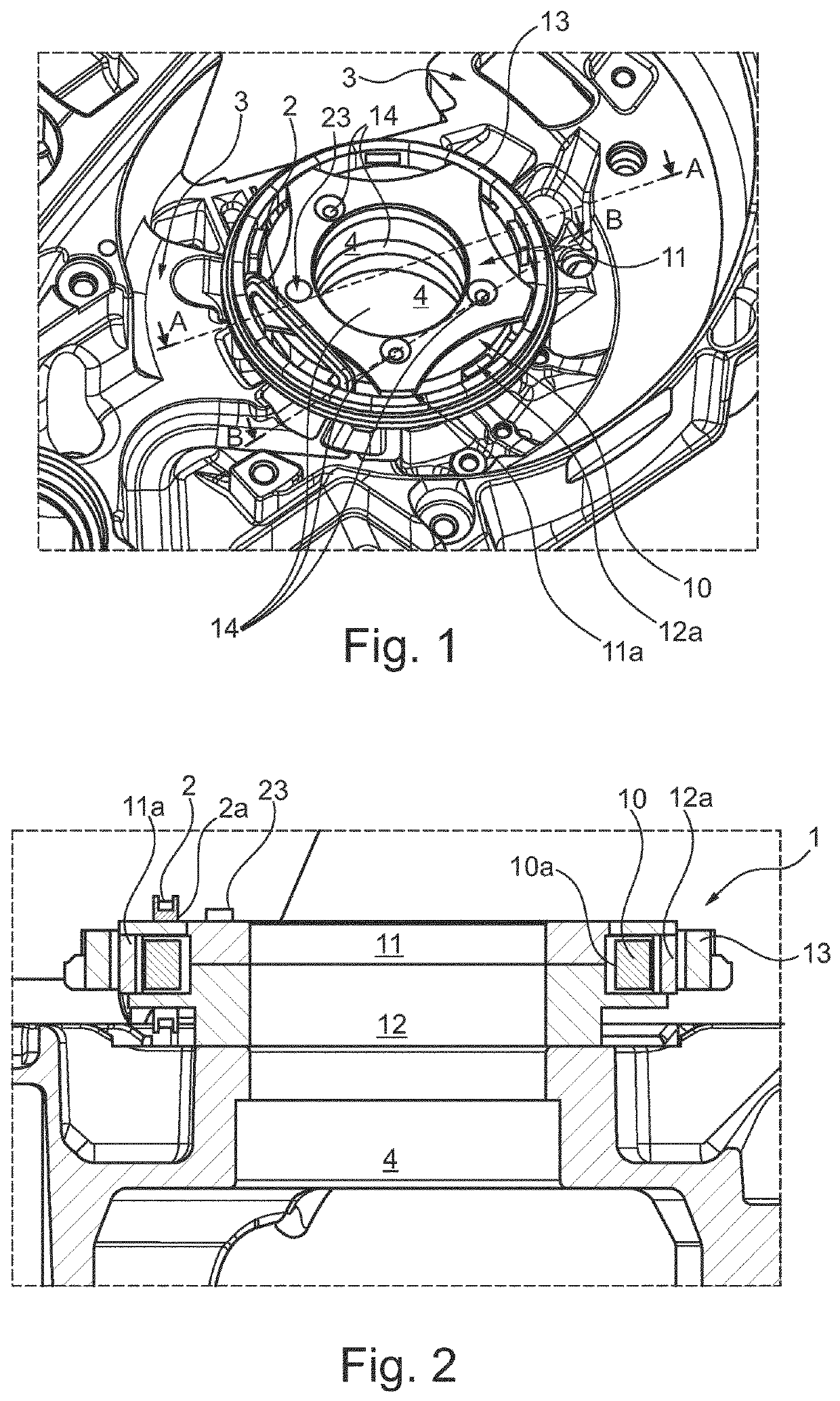
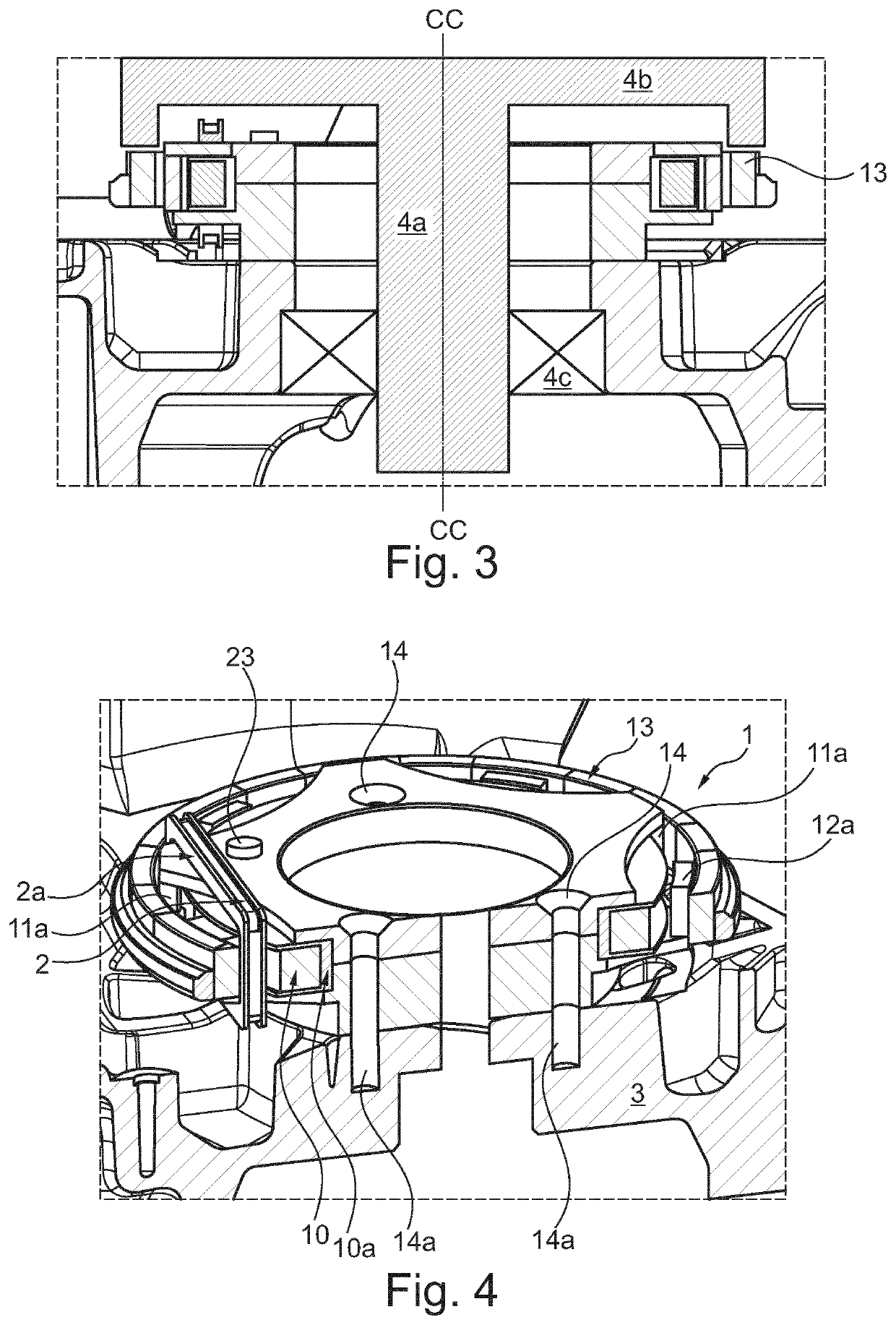
[0031]In FIG. 1 is the inventive claw generator 1 mounted in an engine casing 3 of a hand-held engine around a bearing seat 4 for a crankshaft. The engine casing 3 is conventionally casted in aluminum or any other light weight alloy. The claw generator consists of two basic part. The first basic part is a stationary part with a stationary circular power coil winding 10 clamped between an upper claw half 11 (as seen in FIG. 1) and lower claw half 12. The two claw halves 11,12 are firmly attached to the engine casing 3 with screws (not shown per se) applied through several mounting holes 14 ending with threaded screw holes 14a in the engine casing 3. Each claw half consists of a flat pentahedron shaped disc with a leg on each point end of the pentahedron shaped disc, wherein each leg is bent orthogonally to the orientation of the disc.

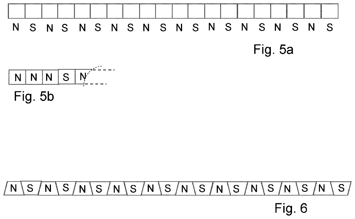
[0032]The upper and lower claw halves are mounted together such that the legs of one claw half lies between legs of the opposite claw half, i.e. such th...


PUM


Abstract

A magneto ignition system for battery less hand-held combustion engines includes a claw generator with a stationary circular power coil winding enclosed by two iron claw halves and with a rotating flywheel magnet ring with multiple magnetic poles. The stationary circular coil winding includes a trigger coil with a stationary coil winding arranged in a plane orthogonal to the stationary circular power coil winding. The magneto ignition system further includes an engine control module ECM for establishment of appropriate ignition timing, and an ignition coil module ICM. The stationary circular power coil winding may provide the electrical power supply to both the ignition timing module ECM and the ignition coil module ICM.

Description

BACKGROUND OF THE INVENTION[0001]The invention relates to Magneto ignition system for battery less hand-held combustion engines.PRIOR ART[0002]Several flywheel magneto systems for handheld engines have been developed over the years, said flywheel or crankshaft driven magneto systems providing both the triggering pulse for the ignition start as well as power supply for the ignition and / or other electrically appliances such as an electric lamp (for night operations), electrically heated handles, or other electrical features of the hand held combustion engine driven tools.[0003]Already in 1976 was U.S. Pat. No. 39,452,501 (Motorola) published which used a flywheel alternator that included separate trigger coil windings for each cylinder and an additional coil winding providing power to run other electrical appliances. A rotor with circumferentially arranged permanent magnets with opposite polarity induced a trigger pulse in a stationary coil only once each flywheel revolution, and elec...

Claims


Application Information

Patent Timeline
Patent Type & Authority Patents(United States)
IPC IPC(8): F02P1/02H02K21/22F02P7/067F02M51/00H02K1/14F02P1/04
CPCF02P1/02F02M51/005F02P1/04F02P7/067H02K1/145H02K21/222H02K21/227F02P1/08F02P2017/125F02P5/152F02P1/005H02K21/048F02B63/04H02K1/243H02K21/22
Inventor BENGTSSON, JÖRGENGUSTAFSSON, BERTSVENSSON, LARS
Owner SEM AB
Why Eureka
Try Eureka