Optical fiber testing method and optical fiber testing device

a testing method and optical fiber technology, applied in the direction of testing fibre optics/optical waveguide devices, instrumentation, structural/machine measurement, etc., can solve the problem that the transmission capacity of single-mode fiber currently used as a transmission medium is approaching its limi

Active Publication Date: 2022-07-19
NIPPON TELEGRAPH & TELEPHONE CORP
View PDF5 Cites 2 Cited by
  • Summary
  • Abstract
  • Description
  • Claims
  • Application Information

AI Technical Summary

Benefits of technology

[0014]The present invention can provide an optical fiber test method and an optical fiber test apparatus for measuring a mode dependent loss and an inter-modal crosstalk in a fundamental mode and a first higher-order mode at a connection point of a few-mode fiber.

Problems solved by technology

On the other hand, transmission capacity of single mode fiber that is currently used as a transmission medium is approaching its limit.

Method used


Image

  • Optical fiber testing method and optical fiber testing device
  • Optical fiber testing method and optical fiber testing device

Examples


Embodiment Construction

[0018]Hereinafter, embodiments of the present invention will be described with reference to the drawings. The embodiments described below are examples of the present invention, and the present invention is not limited to the following embodiments. In this specification and the drawings, constituent elements having the identical reference signs are assumed to be mutually the same.

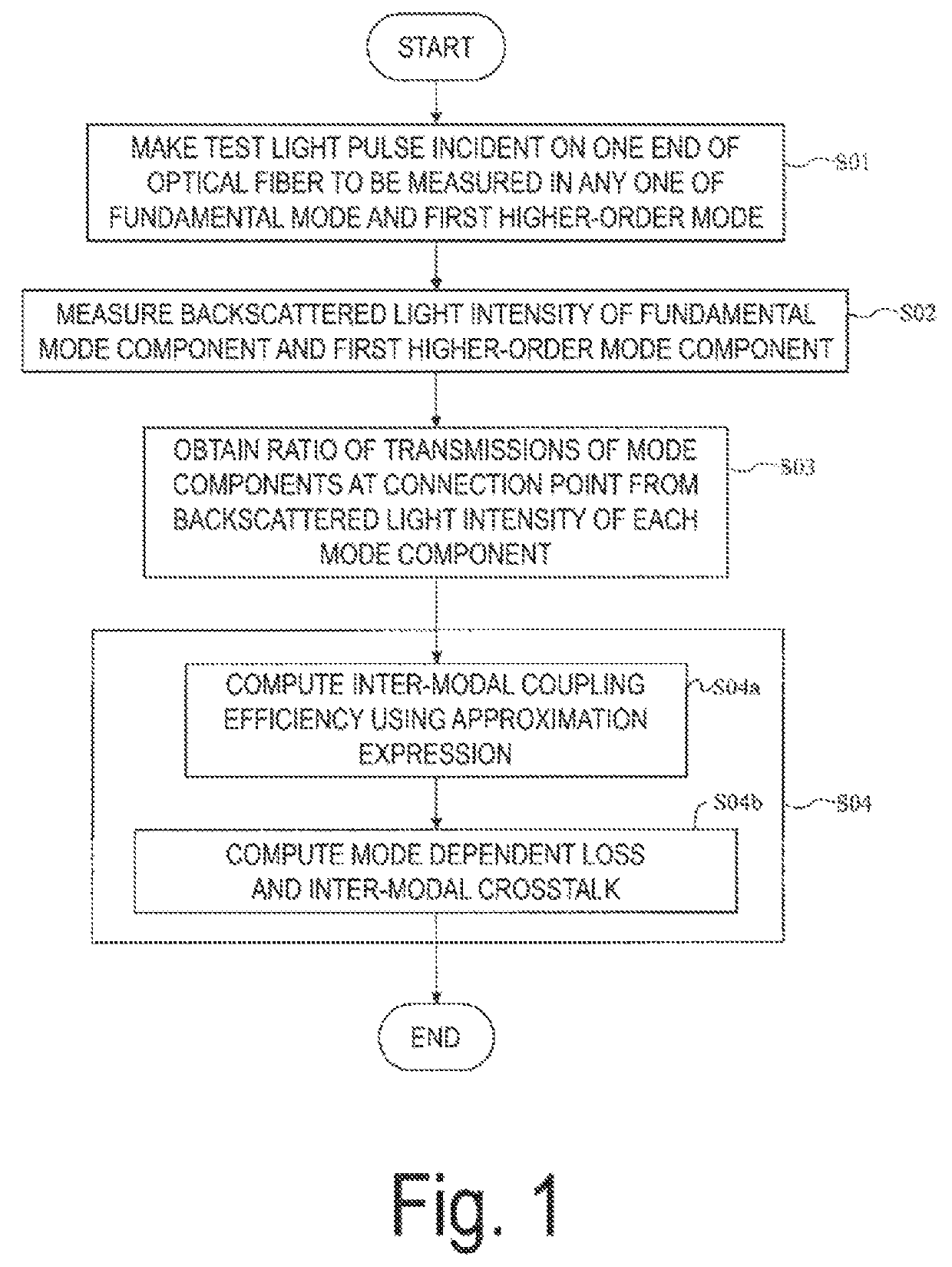
[0019]FIG. 1 is a process chart for explaining an optical fiber test method according to the present embodiment. The optical fiber test method is characterized by performing a light incident procedure S01, a measurement procedure S02, an acquisition procedure S03, and a calculation procedure S04 described below. The light incident procedure S01 makes a test light pulse of a wavelength capable of propagating in a fundamental mode and a first higher-order mode be incident, in any one of the fundamental mode or the first higher-order mode, on one end of an optical fiber under test in which two of the same type ...


PUM

PropertyMeasurementUnit
mode field diameteraaaaaaaaaa
optical fiber testaaaaaaaaaa

Abstract

The present invention has an object to provide an optical fiber test method and an optical fiber test apparatus for measuring a mode dependent loss and an inter-modal crosstalk in a fundamental mode and a first higher-order mode at a connection point of a few-mode fiber. In the optical fiber test method and test apparatus according to the present invention, the mode dependent loss and the inter-modal crosstalk in the fundamental mode and the first higher-order mode at the connection point are calculated by using an approximation expression of an inter-modal coupling efficiency that is obtained in approximating electric field distributions of the fundamental mode and the first higher-order mode in a few-mode fiber by Gaussian function and Hermite Gaussian function.

Description

CROSS-REFERENCE TO RELATED APPLICATIONS[0001]This application is a 371 U.S. National Phase of International Application No. PCT / JP2019 / 023569 filed on Jun. 13, 2019, which claims priority to Japanese Application No. 2018-193530 filed on Oct. 12, 2018. The entire disclosures of the above applications are incorporated herein by reference.TECHNICAL FIELD[0002]The present disclosure relates to a test method and a test apparatus for measuring a mode dependent loss and an inter-modal crosstalk in a few-mode optical fiber.BACKGROUND ART[0003]With the increase in large-volume content such as movies and games, and the spread of smartphones, traffic amounts in optical fiber networks have been increasing every year. On the other hand, transmission capacity of single mode fiber that is currently used as a transmission medium is approaching its limit. As one technique for addressing future traffic increases, mode multiplexing transmission using a few-mode fiber has been focused on. In this techn...

Claims


Application Information

Patent Timeline
Patent Type & Authority Patents(United States)
IPC IPC(8): G01M11/00
CPCG01M11/3109G01M11/3145
Inventor NAKAMURA, ATSUSHIOKAMOTO, KEIJIOSHIDA, HIROYUKI
Owner NIPPON TELEGRAPH & TELEPHONE CORP
Why Eureka
Try Eureka