
Method for producing holograms

a holographic display and hologram technology, applied in the field of hologram generation, can solve the problems of increasing the requirements in relation to the hardware required and the energy consumption for real-time calculation of holograms, holographic displays or display devices represent substantially greater challenges, and slm could no longer be carried out straightforwardly with a fourier transform or fresnel transform

Active Publication Date: 2022-07-26
SEEREAL TECHNOLOGIES
View PDF7 Cites 0 Cited by
  • Summary
  • Abstract
  • Description
  • Claims
  • Application Information

AI Technical Summary

Benefits of technology

The present invention provides a method for generating and calculating holograms that allows for a high quality reconstructed scene and avoids crosstalk in the edge region of a virtual visibility region. The method is also able to achieve real-time calculation of a hologram and reduce the impact of diffraction effects on the virtual visibility region, resulting in improved quality of the reconstructed scene even on a curved or tilted surface. Additionally, the invention aims to achieve a high reconstruction quality in a holographic display with a large field of view.

Problems solved by technology

In comparison with autostereoscopic displays or display devices, holographic displays or display devices represent substantially greater challenges in relation to the resolution of a spatial light modulation device contained in the holographic display and used for encoding a hologram, as well as the computational effort of the hologram.
However, the method increases the requirements in relation to the hardware required and the energy consumption for real-time calculation of holograms.
Although the preferably three-dimensional scene can still be decomposed into depth planes and a transformation of these depth planes into the virtual visibility region can be carried out, a transformation from the virtual visibility region into the plane, which is curved or is tilted with respect to the virtual visibility region, of the SLM could however no longer be carried out straightforwardly with a Fourier transform or Fresnel transform.
Then, for object points of a preferably three-dimensional scene at the edge of the field of view, under certain circumstances the calculation with the Fourier transform method generates subholograms which could only lead to an insufficient reconstruction of the object point.
This diffraction at the edges of the sharply bounded subholograms, however, leads to a virtual visibility region whose edges are not sharply delimited but are blurred or fuzzy, or even indistinct.

Method used


Image

  • Method for producing holograms
  • Method for producing holograms
  • Method for producing holograms

Examples


Embodiment Construction

[0153]It should briefly be mentioned that elements / parts / components which are the same also have the same references in the figures.

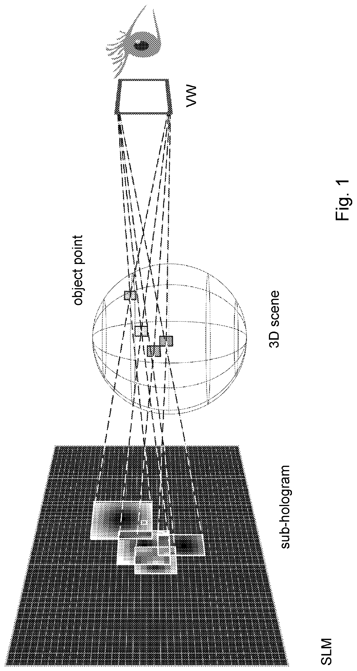
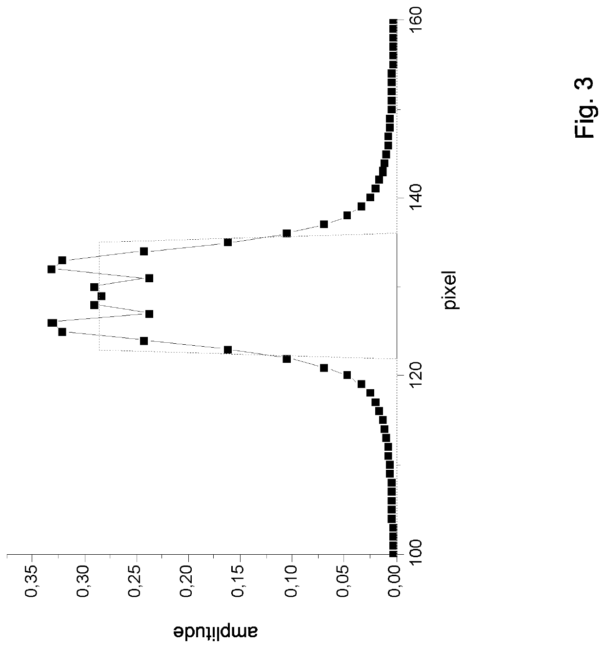
[0154]With the aid of FIGS. 2 to 5, a more detailed description will be given of the generation and calculation of encoding regions on the basis of subholograms on a spatial light modulation device (SLM) of a holographic display, in which the associated object points each have small distances with respect to the SLM.

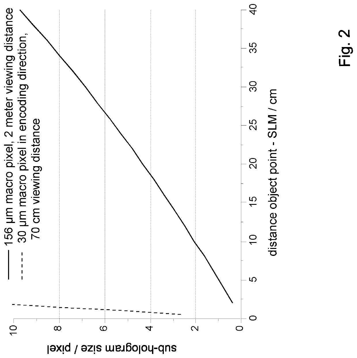
[0155]With respect to the size of a subhologram on the SLM by means of an analytical calculation or by means of the known or conventional projection method, for different types and sizes of an SLM, reference is made in general to FIG. 2 in which the size of the subhologram on the SLM is plotted in pixels against the distance of an object point of a scene to be reconstructed from the SLM. The solid curve shows subhologram sizes as a function of the object point distance with respect to the SLM for an SLM with a resolution of about five megapi...


PUM


Abstract

The invention relates to a method for generating holograms for encoding in a spatial light modulation device for a holographic display for representing a two- and / or three-dimensional scene. The two- and / or three-dimensional scene is decomposed into object points and encoded in a hologram, which is subdivided into subholograms, in the spatial light modulation device. The object points of the scene are encoded into encoding regions on the spatial light modulation device. A size and / or shape of the encoding region is selected in relation to a size and / or shape of a subhologram, assigned to the encoding region, in such a way that crosstalk of higher diffraction orders in a virtual visibility region is reduced.

Description

CROSS REFERENCE TO RELATED APPLICATIONS[0001]This application claims the priority of PCT / EP2017 / 061846, filed on May 17, 2017, which claims priority to European Application No. EP 16170063.8, filed on May 18, 2016; and European Application No. EP 16185261.1, filed on Aug. 23, 2016, the entire contents of each of which are incorporated fully herein by reference.BACKGROUND OF THE INVENTION[0002]The invention relates to a method for generating holograms for encoding in a spatial light modulation device for a holographic display for representing a two- and / or three-dimensional scene. Furthermore, the invention also relates to a light modulation apparatus into which a hologram is encoded according to the method according to the invention, and to a display, in particular a holographic display.[0003]In comparison with autostereoscopic displays or display devices, holographic displays or display devices represent substantially greater challenges in relation to the resolution of a spatial li...

Claims


Application Information

Patent Timeline
IPC IPC(8): G03H1/08G03H1/16G03H1/22
CPCG03H1/0808G03H1/16G03H1/2202G03H1/2294G03H2001/0825G03H2001/0833G03H2001/2236G03H2001/2239G03H2001/2255G03H2210/452G03H2210/454G03H2210/46
Inventor LEISTER, NORBERTHAUSSLER, RALFFUTTERER, GERALD
Owner SEEREAL TECHNOLOGIES
Learn More