
Method and system for preparing block diagrams for code generation

a block diagram and code generation technology, applied in the field of method and system for preparing block diagrams for code generation, can solve the problems of limited usefulness of current methods for preparing for code generation, cumbersome setting properties individually for each variable,

Active Publication Date: 2022-08-02
DSPACE DIGITAL SIGNAL PROCESSING & CONTROL ENG
View PDF8 Cites 0 Cited by
  • Summary
  • Abstract
  • Description
  • Claims
  • Application Information

AI Technical Summary

Benefits of technology

The invention provides a method for improving the code generation settings for hierarchical blocks that are commonly used in electronic control units. By taking into account the maximum and minimum values of the output ports, the code generation settings for control algorithms comprising feedback loops are improved. This method allows for a comfortable and efficient process to adapt the code generation settings for these blocks, reducing errors and warnings during processing. The scaling parameters for subordinate blocks can be determined iteratively, and the order of preparing subordinate blocks is predefined for the first block. The minimum and maximum values for the input and output ports can be stored in a data definition tool, and the scaling parameters are determined based on these values. The method also allows for suggesting changes to the maximum and minimum values, reducing the need for time-consuming debugging. Overall, this invention improves the quality of control and efficiency of code generation for hierarchical blocks.

Problems solved by technology

Setting properties individually for each variable is very cumbersome; defining generation settings for different classes of variables and assigning a variable class to each variable allows for reducing the effort.
Especially for more complex hierarchical blocks comprising a plurality of subordinate blocks, current methods of preparing for code generation are still of limited usefulness.

Method used


Image

  • Method and system for preparing block diagrams for code generation
  • Method and system for preparing block diagrams for code generation
  • Method and system for preparing block diagrams for code generation

Examples


Embodiment Construction

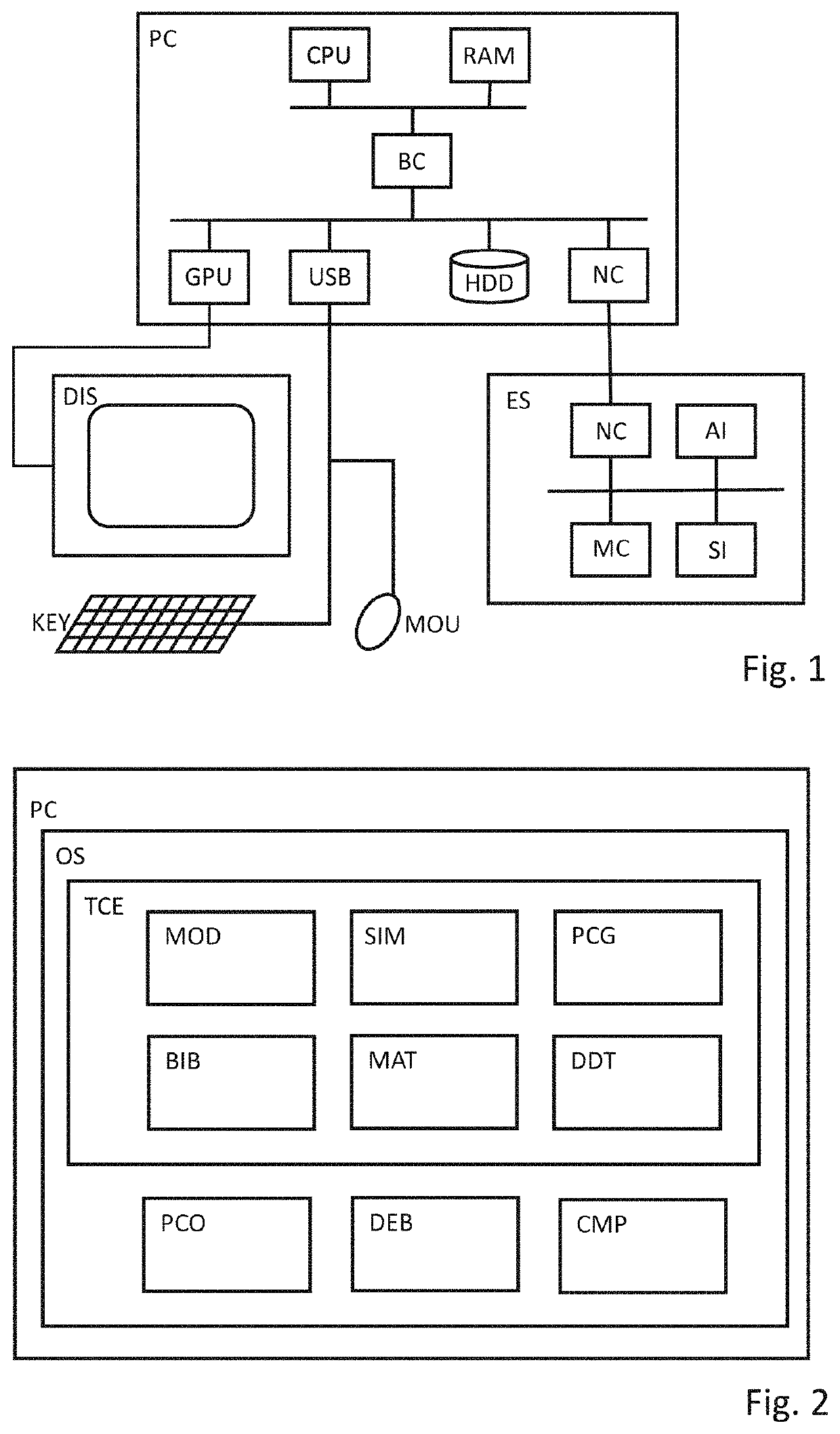
[0033]FIG. 1 illustrates an exemplary embodiment of a computer system.

[0034]The shown embodiment comprises a host computer PC with a display DIS and human interface devices such as a keyboard KEY and a mouse MOU; further, an embedded system ES is depicted, which may e.g. be used for a processor-in-the-loop simulation.

[0035]The host computer PC comprises at least one processor CPU with one or multiple cores, a random-access memory RAM and a number of devices connected to a local bus (such as PCI Express), which exchanges data with the CPU via a bus controller BC. The devices comprise e.g. a graphics-processing unit GPU for driving the display, a controller USB for attaching peripherals, a non-volatile memory HDD such as a hard disk or a solid-state disk, and a network interface NC. Preferably, the non-volatile memory comprises instructions that, when executed by one or more cores of the processor CPU, cause the computer system to carry out a method according to one of the claims.

[003...


PUM


Abstract

A method for preparing block diagrams having one or more blocks for code generation in a computing environment comprising a model editor, a data definition tool and a code generator. The block diagram is opened in the model editor, wherein a first block is a hierarchical block comprising a plurality of subordinate blocks, at least one input port and at least one output port connected by signals. Minimum values and maximum values are received for the input and output ports, determining scaling parameters for the input and output ports based on the received minimum and maximum values. Scaling parameters are determined for each subordinate block in the first block, wherein the scaling parameters of at least one subordinate block are determined based on the scaling parameters of at least one output port. Also, a method for generating program code, a non-transitory computer readable medium and a computer system are provided.

Description

[0001]This nonprovisional application claims priority under 35 U.S.C. § 119(a) to German Patent Application No. 10 2019 120 829.7, which was filed in Germany on Aug. 1, 2019, and which is herein incorporated by reference.BACKGROUND OF THE INVENTIONField of the Invention[0002]The present invention relates to generating code from block diagrams and to preparing block diagrams for code generation.Description of the Background Art[0003]Electronic control units (ECUs) are ubiquitous especially in automotive applications; generally, they may contain a processor, such as a microcontroller, one or more sensor interfaces and one or more circuits to control an actuator. Current parameters of a physical process are preferably determined using the signals of the one or more sensors connected to the sensor interfaces. Based on a predefined control strategy, the processor may control the one or more circuits to apply the actuators for influencing the physical process. For example, an ECU may be u...

Claims


Application Information

Patent Timeline
Patent Type & Authority Patents(United States)
IPC IPC(8): G06N20/00G06F8/35G06F8/36G06F8/34
CPCG06F8/35G06F8/34G06F8/36G06F9/455
Inventor SCHERLE, JOHANNESJOHANSSON, ANDERSGRAJETZKY, OLAF
Owner DSPACE DIGITAL SIGNAL PROCESSING & CONTROL ENG
Learn More