Supercharge Your Innovation With Domain-Expert AI Agents!

Deep-learning based structure reconstruction method and apparatus

a structure reconstruction and deep learning technology, applied in the field of superresolution fluorescence microscopy image generation, can solve the problems of long imaging time, increased damage to live samples, and inability to solve the above problem completely

Active Publication Date: 2022-08-02
KING ABDULLAH UNIV OF SCI & TECH
View PDF5 Cites 1 Cited by
  • Summary
  • Abstract
  • Description
  • Claims
  • Application Information

AI Technical Summary

Benefits of technology

The method achieves more accurate and realistic reconstructions of biological structures with sub-diffraction limit resolution, significantly reducing imaging time and computational expense compared to existing methods, while providing a trade-off between accuracy and speed.

Problems solved by technology

When compared with STED, RESOLFT and SIM, the PALM and STORM approaches do not need specialized microscopes, but the localization techniques of PALM and STORM approaches require the fluorescence emission from individual fluorophores to not overlap with each other, leading to long imaging time and increased damage to live samples (Lippincott-Schwartz and Manley, 2009).
More recent methods (Holden et al., 2011; Huang et al., 2011; Quan et al., 2011; Zhu et al., 2012) alleviate the long exposure problem by developing multiple-fluorophore fitting techniques to allow relatively dense fluorescent data, but still do not solve the above problem completely.
However, there are two fundamental differences between the SISR and super-resolution fluorescence microscopy.
Second, the nature of SISR ensures that there are readily a large amount of data to train deep learning models, whereas for fluorescence microscopy, there are only limited time-series datasets.
Furthermore, most of the existing fluorescence microscopy datasets do not have the ground-truth high-resolution images, which make supervised deep learning infeasible and impractical.

Method used


Image

  • Deep-learning based structure reconstruction method and apparatus
  • Deep-learning based structure reconstruction method and apparatus
  • Deep-learning based structure reconstruction method and apparatus

Examples


Embodiment Construction

[0024]The following description of the embodiments refers to the accompanying drawings. The same reference numbers in different drawings identify the same or similar elements. The following detailed description does not limit the invention. Instead, the scope of the invention is defined by the appended claims.

[0025]Reference throughout the specification to “one embodiment” or “an embodiment” means that a particular feature, structure or characteristic described in connection with an embodiment is included in at least one embodiment of the subject matter disclosed. Thus, the appearance of the phrases “in one embodiment” or “in an embodiment” in various places throughout the specification is not necessarily referring to the same embodiment. Further, the particular features, structures or characteristics may be combined in any suitable manner in one or more embodiments.

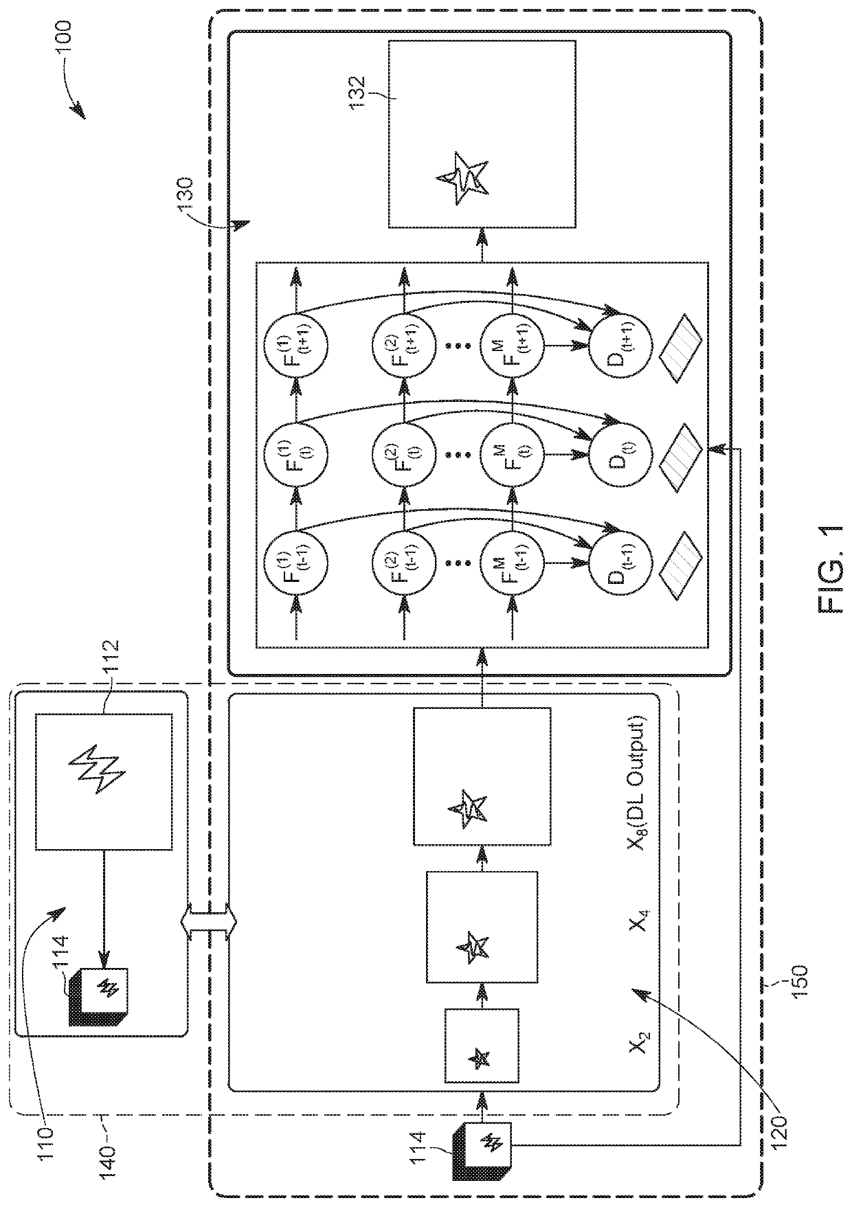
[0026]According to an embodiment, there is a method for deep-learning structure reconstruction based on a time-series ...


PUM

PropertyMeasurementUnit
structure simulationaaaaaaaaaa
super-resolution fluorescence microscopyaaaaaaaaaa
timeaaaaaaaaaa

Abstract

A method for structure simulation for super-resolution fluorescence microscopy, the method including receiving a first image having a first resolution, which is indicative of a distribution of fluorophores; applying a Markov model to the fluorophores to indicate an emission state of the fluorophores; generating a plurality of second images, having the first resolution, based on the first image and the Markov model; adding DC background to the plurality of second images to generate a plurality of third images, having the first resolution; downsampling the plurality of third images to obtain a plurality of fourth images, which have a second resolution, lower than the first resolution; and generating a time-series, low-resolution images by adding noise to the plurality of fourth images. The time-series, low-resolution images have the second resolution.

Description

CROSS-REFERENCE TO RELATED APPLICATIONS[0001]This application is a U.S. National Stage Application of International Application No. PCT / IB2018 / 059636, filed on Dec. 4, 2018, which claims priority to U.S. Provisional Patent Application No. 62 / 621,642, filed on Jan. 25, 2018, entitled “DLBI: DEEP LEARNING GUIDED BAYESIAN INFERENCE FOR STRUCTURE RECONSTRUCTION OF SUPER-RESOLUTION FLUORESCENCE MICROSCOPY,” the disclosures of which are incorporated herein by reference in their entirety.BACKGROUNDTechnical Field[0002]Embodiments of the subject matter disclosed herein generally relate to a system and method for generating a super-resolution fluorescence microscopy image, and more specifically, to techniques for structure reconstruction of super-resolution fluorescence microscopy.Discussion of the Background[0003]Fluorescence microscopy imaging with a resolution beyond the diffraction limit of light (which is called super-resolution in the art) is playing an important role in biological sci...

Claims


Application Information

Patent Timeline
Patent Type & Authority Patents(United States)
IPC IPC(8): G06T3/40G01N21/64G06N3/08G06T5/00G06T5/20G06T5/50
CPCG06T3/4076G01N21/6458G06N3/08G06T3/4046G06T5/002G06T5/20G06T5/50G06T2207/10056G06T2207/10064G06T2207/20084G06T5/70
Inventor GAO, XINLI, YUHAN, RENMIN
Owner KING ABDULLAH UNIV OF SCI & TECH
Features
  • R&D
  • Intellectual Property
  • Life Sciences
  • Materials
  • Tech Scout
  • Unparalleled Data Quality
  • Higher Quality Content
  • 60% Fewer Hallucinations
Learn More