Heat exchange device, heat exchange system, and heat exchange method

a heat exchange device and heat exchange technology, applied in the direction of indirect heat exchangers, lighting and heating apparatuses, machines' operation modes, etc., can solve the problems of extremely low efficiency of power generation using prime movers, limited cases that can be used for waste heat power generation, and ineffective conversion of consummed amount into heat, so as to achieve efficient power generation and maintain heat transferability

Active Publication Date: 2022-08-09
NEC CORP
View PDF13 Cites 2 Cited by
  • Summary
  • Abstract
  • Description
  • Claims
  • Application Information

AI Technical Summary

Benefits of technology

[0022]According to the present invention, power generation can be efficiently performed while maintaining heat transferability.

Problems solved by technology

For example, an internal combustion engine used for an automobile, a generator, and the like consumes energy in order to acquire motive power and electric power, and a considerable proportion of the consumed amount is ultimately converted to heat.
When heat continues to be generated, an internal temperature of the internal combustion engine rises, which may cause an equipment failure, and therefore, it is necessary to discharge unnecessary heat for the purpose of equipment maintenance.
However, power generation using a prime mover is extremely decreased in efficiency when a temperature of a heat source decreases or a scale of power generation decreases, and therefore, cases that can be used for waste heat power generation are limited.

Method used


Image

  • Heat exchange device, heat exchange system, and heat exchange method
  • Heat exchange device, heat exchange system, and heat exchange method
  • Heat exchange device, heat exchange system, and heat exchange method

Examples


first example embodiment

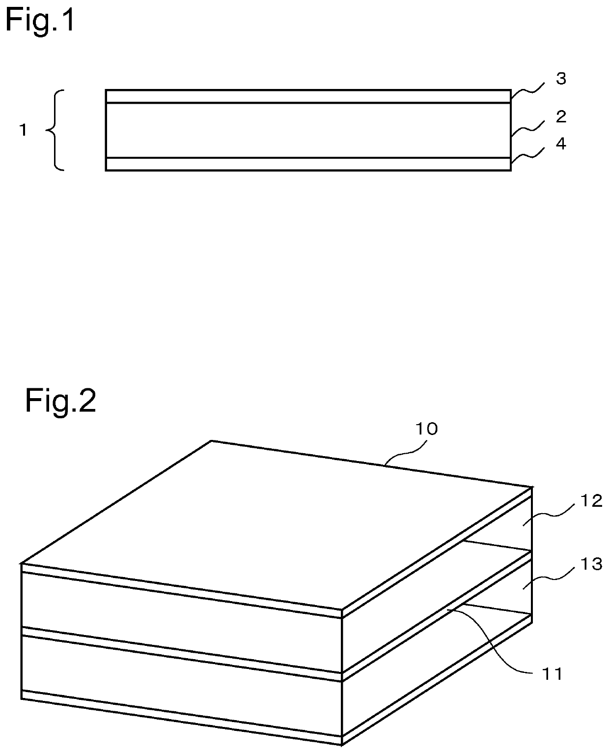
[0040]The first example embodiment of the present invention will be described in detail with reference to the drawings. FIG. 1 illustrates overview of a configuration of a heat exchange device according to the first example embodiment. The heat exchange device of the present example embodiment includes a heat exchange section 1 and a magnetic body 2. The heat exchange section 1 includes a first heat transfer interface 3 in contact with a heat source and a second heat transfer interface 4 in contact with a heat reservoir having a temperature different from that of the heat source. The magnetic body 2 is sandwiched between the first heat transfer interface 3 and the second heat transfer interface 4 of the heat exchange section 1, and has a magnetization component in the direction intersecting the heat flux generated between the first heat transfer interface 3 and the second heat transfer interface 4.

[0041]The heat exchange device of the present example embodiment includes a magnetic b...

second example embodiment

[0042]The second example embodiment of the present invention will be described in detail with reference to the drawings. FIG. 2 is a figure illustrating overview of a configuration of a heat exchange device 10 of the second example embodiment of the present invention. The heat exchange device 10 includes a heat exchange section 11, a first flow path 12, and a second flow path 13. The heat exchange device 10 of the present example embodiment is a flat plate heat exchange device that acquires electric power by the thermoelectromotive force generated by the temperature difference at the heat exchange section 11 provided between the first flow path 12 through which the fluid sent from the heat source flows and the second flow path 13 through which the fluid sent from the heat reservoir flows.

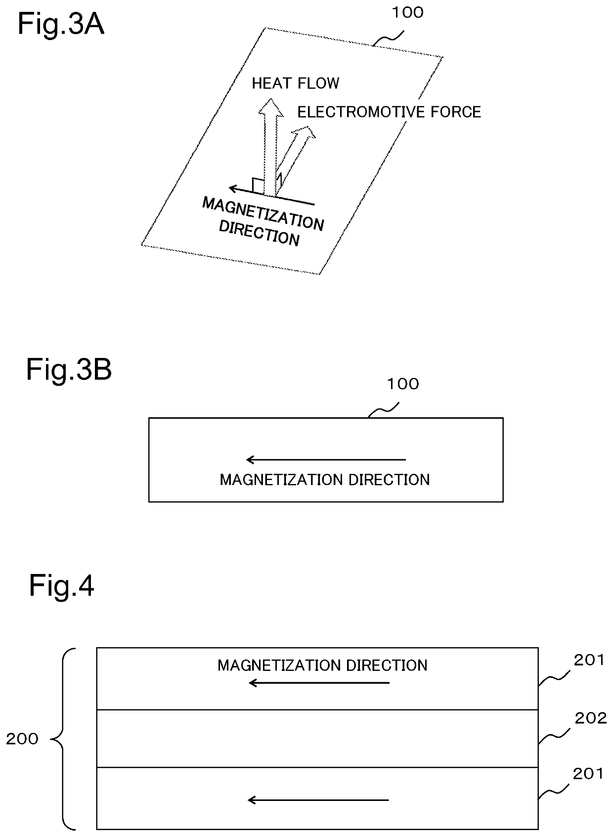
[0043]The heat exchange section 11 is a flat plate thermoelectric conversion member which acquires electric power on the basis of the thermoelectromotive force generated by the temperature differenc...

third example embodiment

[0079]The third example embodiment of the present invention will be described in detail with reference to the drawings. FIG. 7 is a figure illustrating overview of a configuration of a heat exchange device 20 of the present example embodiment. The heat exchange device 20 of the present example embodiment includes a plurality of heat exchange sections 21, a first flow path 22, a second flow path 23, and a fin 24. The heat exchange device 20 of the present example embodiment is characterized in that the thermal conductivity from each fluid is improved by forming the fin 24 in each flow path between the heat exchange sections 21.

[0080]For the heat exchange section 21, a thermoelectric conversion member similar to the heat exchange section 11 of the second example embodiment can be used. The direction of magnetization of the thermoelectric conversion member of the heat exchange section 21 is set according to the direction in which heat flow is generated and the direction in which power ...


PUM


Abstract

[Problem] To provide a heat exchange device with which efficient electric power generation can be performed while transfer of a heat amount is maintained. [Solution] A heat exchange device comprising a heat exchange section 1 and a magnetic body 2. The heat exchange section 1 includes a first heat transmission interface 3 in contact with a heat source, and a second heat transmission interface 4 in contact with a heat bath having a temperature different from that of the heat source. The magnetic body 2 is interposed between the first heat transmission interface 3 and the second heat transmission interface 4 of the heat exchange section 1, and includes a magnetization component in a direction intersecting a heat flux produced between the first heat transmission interface 3 and the second heat transmission interface 4.

Description

CROSS REFERENCE TO RELATED APPLICATIONS[0001]This application is a National Stage of International Application No. PCT / JP2018 / 009714 filed Mar. 13, 2018, claiming priority based on Japanese Patent Application No. 2017-054446 filed on Mar. 21, 2017, the entire contents of which are incorporated by reference.TECHNICAL FIELD[0002]The present invention relates to a heat exchange device, and more particularly to a technique for generating electricity by thermoelectric conversion at the time of heat exchange.BACKGROUND ART[0003]There is a system intended for the purpose of transfer of a quantity of heat from a high-temperature heat source to a low-temperature heat reservoir, that is, performing heat exchange with a certain magnitude or more. For example, an internal combustion engine used for an automobile, a generator, and the like consumes energy in order to acquire motive power and electric power, and a considerable proportion of the consumed amount is ultimately converted to heat. Whe...

Claims


Application Information

Patent Timeline
Patent Type & Authority Patents(United States)
IPC IPC(8): H01L35/30H01L37/00F25B21/02H01L43/02
CPCH01L35/30F25B21/02H01L37/00F25B2321/0252H01L43/02F28D20/00F28D1/05366Y02E60/14H10N15/20H10N10/13H10N15/00H10N50/80
Inventor ISHIDA, MASAHIKOKIRIHARA, AKIHIROIWASAKI, YUMA
Owner NEC CORP
Why Eureka
Try Eureka