Supercharge Your Innovation With Domain-Expert AI Agents!

Malleable retractor

a surgical retractor and malleable technology, applied in the field of malleable surgical retractors, can solve the problems of obscuring the surgical field from the surgeon's view, affecting the surgeon's freedom to orient the surgical retractor into the desired position,

Active Publication Date: 2022-09-27
ILLUMIX SURGICAL CANADA
View PDF3 Cites 0 Cited by
  • Summary
  • Abstract
  • Description
  • Claims
  • Application Information

AI Technical Summary

Benefits of technology

The present invention is about illuminated malleable surgical retractors and methods for making them. The retractors have a malleable strip with a proximal end and a distal end, and can be bent into different configurations. The malleable strip has an insulative layer with an illumination source disposed over it. The insulative layer can be made of various materials such as polymer, ceramic, or metal. The illumination source can be LEDs, OLEDs, or other light-emitting electronic components. The retractors can also have a flexible charge storage module or a flexible charge dispensing module for supplying power to the illumination source. The invention allows for better illumination in surgery without separating the insulative layer from the malleable strip. The insulative layer can also have a conductor to convey electrical current from the flexible charge storage / charge dispensing module to the planar illumination source. The malleable retractor can also have a control element to regulate the power conveyed from the charge storage / charge Dispensing Module.

Problems solved by technology

However, at times, a surgical instrument and / or other operating room equipment may give rise to shadowing of light from an overhead source intended to illuminate a surgical area of interest.
Further, other instrumentation in and around the surgical field may obscure the surgical field from the surgeon's view.
However, fiber-optics-based illuminated surgical retractors may be attached to cables, such as electrical and / or fiber-optic cables, which may impede a surgeon's freedom to orient a surgical retractor into a desired position.
Additionally, fiber-optics-based retractors may direct illumination predominately along the longer dimension of a surgical retractor, without providing sufficient illumination directly beneath the retractor.

Method used


Image

  • Malleable retractor
  • Malleable retractor
  • Malleable retractor

Examples


embodiment 300

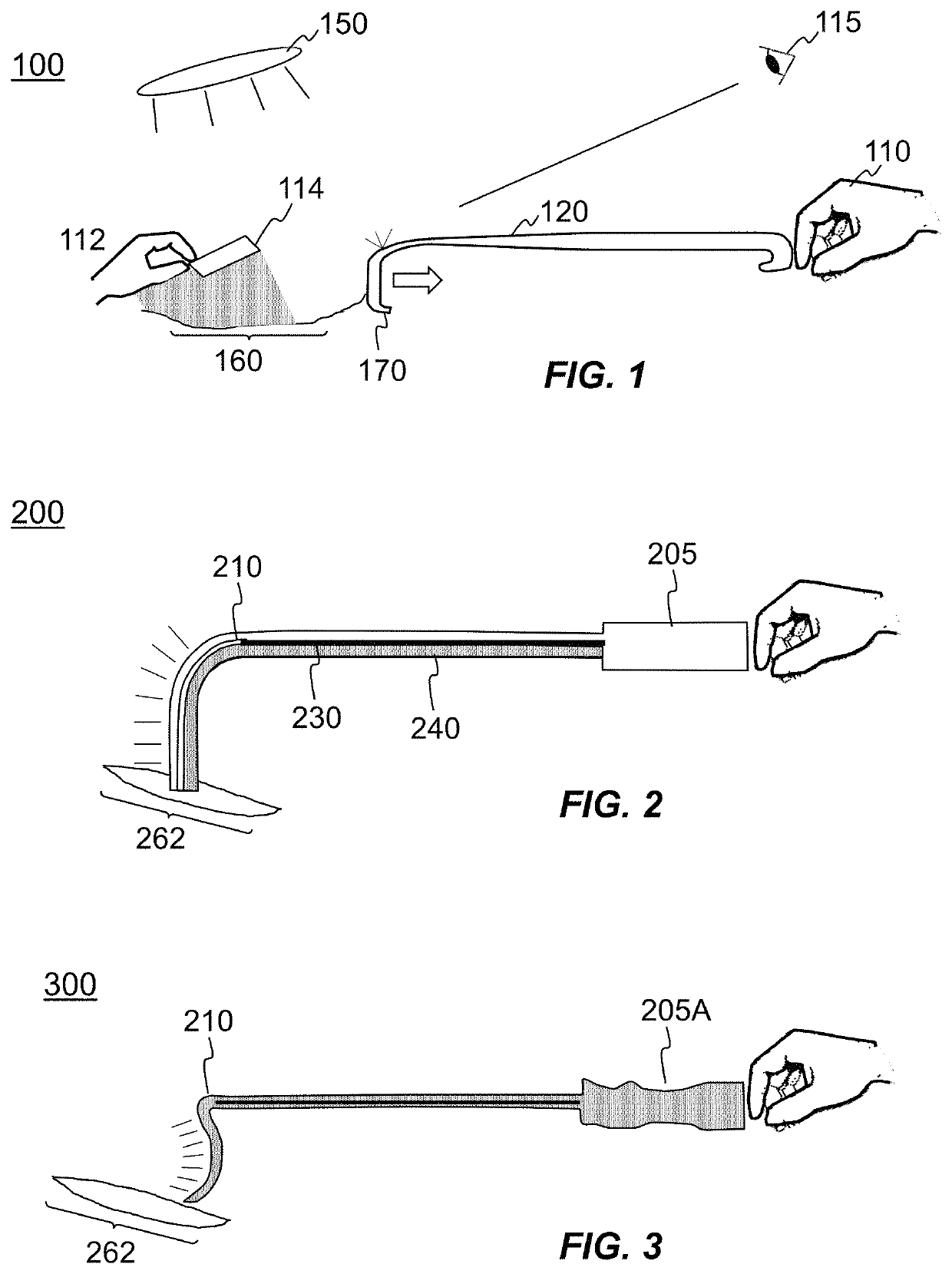
[0044]FIG. 3 is an illustration of a malleable and integrally illuminated surgical retractor showing flexibility of an illuminating end portion and a conformal handgrip according to an embodiment 300. Accordingly, as shown in FIG. 3, handle portion 205A may be formed or molded to comprise features to mate with the shape of a human hand, so as to permit a surgeon to comfortably grip handle portion 205 during surgical procedures. At an opposite end of handle portion 205A, illumination source 210 is shown as being malleable, thereby permitting shaping of an end portion of handle 205 to permit illumination of tight crevices, such as crevice 262, within a human or animal body, for example, or to bend around anatomical structures during surgical procedures.

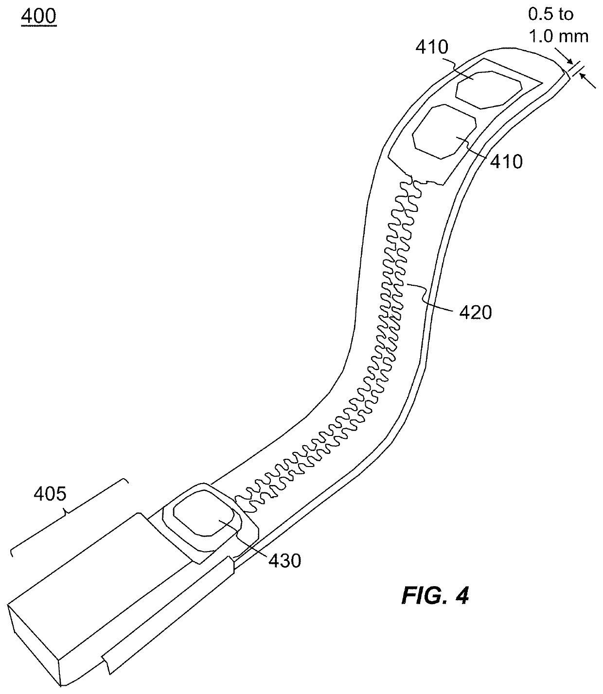
[0045]FIG. 4 is a perspective view of a malleable and integrally illuminated surgical retractor according to an embodiment 400. In embodiment 400, a handle portion 405 comprises a control element 430, which may permit a surgeon, for exa...

embodiment 400

[0046]In the embodiment of FIG. 4, a malleable and integrally illuminated surgical retractor may comprise a shapeable plastic or a thin metallic strip comprising stainless steel or any other metal / metal alloy, comprising a thickness approximately in the range of 0.5-1.0 mm, for example. In embodiments, a layer of stretchable insulative material, such as silicone, thermoplastic polyurethane (TPU), or any type of elastically deformable material (which may comprise a polymeric layer, for example), may be formed or fabricated on or over the malleable strip so as to permit the bending of the retractor without separation of the insulative material from the malleable strip. In this context, the term “elastically deformable material,” such as may be formed or fabricated on or over the malleable strip is defined as a material comprising a substantial portion of a polymeric elastically deformable material, such as silicone, TPU, polyvinyl chloride (PVC), synthetic polymer, transparent ceramic...

embodiment 500

[0048]FIG. 5 is an illustration showing extension and compression of surfaces brought about by bending a portion of malleable and integrally illuminated a surgical retractor according to embodiment 500. As shown in FIG. 5A, meandering conductor line 530 is disposed or deposited on a surface 510 of a portion of a surgical retractor. Thus, responsive to bending or shaping of a portion of a malleable and integrally-illuminated surgical retractor, such as to comprise a bend radius of, for example, less than 1.0 cm, meandering conductor line 530 may undergo stretching or elongation, relative to a flattened or unbent state. In addition, during bending or shaping of the portion of a malleable and integrally illuminated retractor, surface 520 may undergo compression relative to a flattened or unbent state. In embodiments, a portion of the retractor may be bent or shaped to comprise a different bend radius, such as, for example, less than 1.0 cm, such as 0.75 cm, or may be bent or shaped to ...


PUM

PropertyMeasurementUnit
bend radiusaaaaaaaaaa

Abstract

Embodiments of claimed subject matter are directed to a malleable and integrally illuminated surgical retractor. In an embodiment, a malleable steel strip, having a thickness approximately in the range of 0.5-1.0 mm, may form a substrate. An elastically deformable layer, such as a polymeric layer, may be secured to the malleable steel strip. One or more meandering conductive lines, spiral conductors, or conductive inks, which may elongate and / or compress during bending of the substrate, may be secured to the TPU layer. The one or more meandering conductive lines, spiral conductors, or conductive inks may operate to couple current from an electronics module to one or more malleable illumination sources comprising, for example, an organic light-emitting diode (OLED).

Description

CROSS REFERENCE TO RELATED APPLICATIONS[0001]This application is a continuation of U.S. patent application Ser. No. 15 / 642,426, filed Jul. 6, 2017, now U.S. Pat. No. 10,420,539, which is expressly incorporated in its entirety herein by reference.BACKGROUND1. Field[0002]This disclosure relates generally to the field of surgical devices and, more particularly, to one or more approaches toward directing illumination from a surgical device towards a surgical area of interest.2. Information[0003]While performing a surgical procedure, a surgeon may utilize a retractor, which may allow the surgeon to draw lateral and deep layers of tissue away from underlying features and / or structures. Responsive to the drawing or retracting of lateral and deep layers away from underlying features, a surgeon may focus his or her attention on repair, manipulation, and / or replacement of body organs, and / or other anatomical structures including, but not limited to, soft tissue, nerve, venous, arterial, tendi...

Claims


Application Information

Patent Timeline
Patent Type & Authority Patents(United States)
IPC IPC(8): A61B17/02A61B90/30A61B17/00
CPCA61B17/02A61B90/30A61B2017/00017A61B2017/00946A61B2017/0225A61B2090/309
Inventor DUGGAL, ANILDOBROVOLSKIS, PAULKUSTERS, ROEL HSMITS, EDSGER CONSTANT PIETER
Owner ILLUMIX SURGICAL CANADA
Features
  • R&D
  • Intellectual Property
  • Life Sciences
  • Materials
  • Tech Scout
  • Unparalleled Data Quality
  • Higher Quality Content
  • 60% Fewer Hallucinations
Learn More