

Sensorized suspension assembly for vehicles, including a wheel hub unit and a suspension upright or knuckle, and an associated method and wheel hub unit
a technology for suspension assemblies and vehicles, applied in the direction of apparatus for force/torque/work measurement, instruments, transportation and packaging, etc., can solve the problems of not being able to correctly detect the force acting on the tire, complex and costly implementation, and not being able to prove effective in correct detection
- Summary
- Abstract
- Description
- Claims
- Application Information
AI Technical Summary
Benefits of technology
Problems solved by technology
Method used
Image

Examples
Embodiment Construction
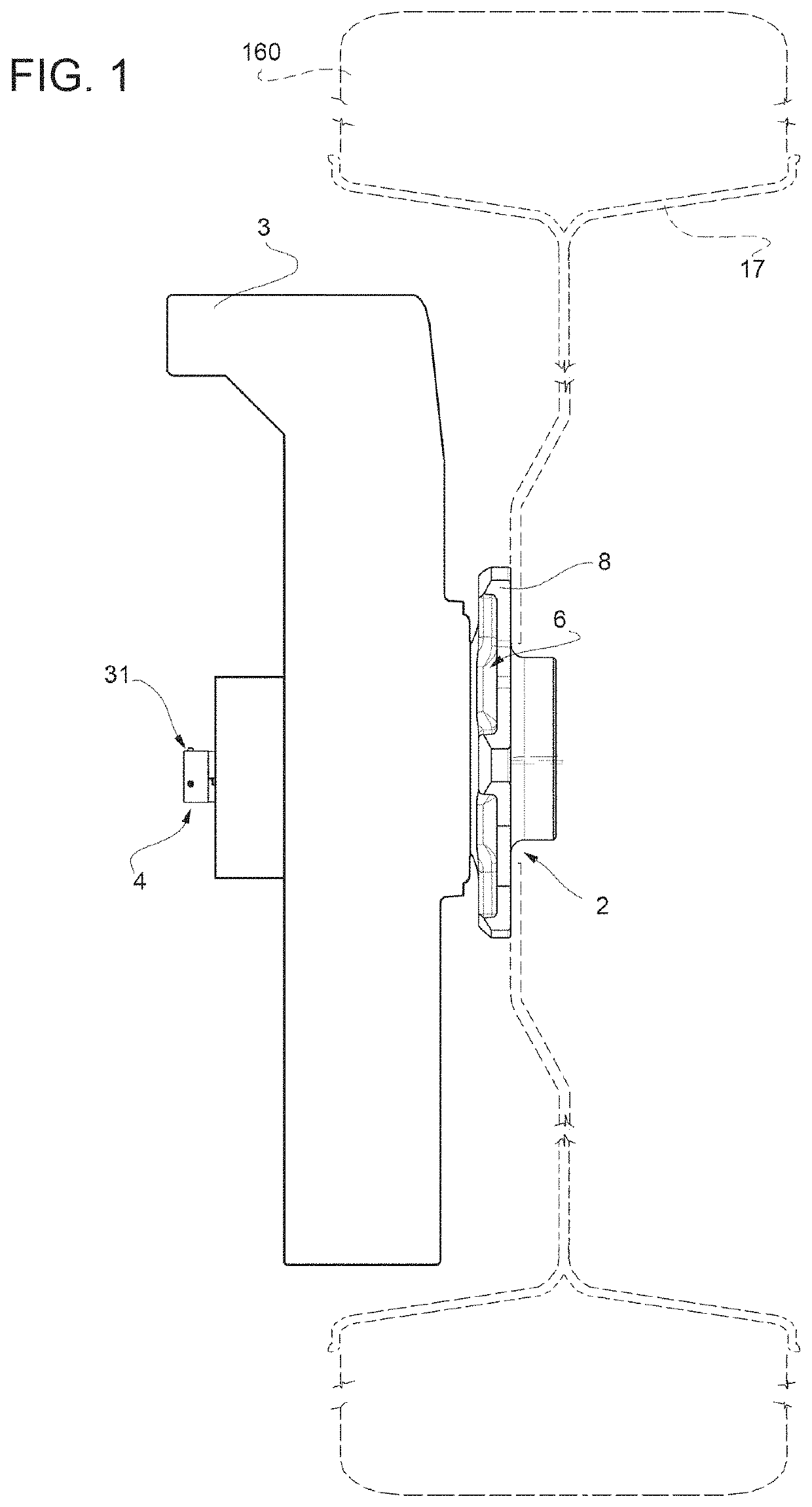
[0012]A suspension assembly for vehicles in accordance with this disclosure includes a wheel hub unit and a suspension upright or knuckle and a sensorized system for detecting in real time the forces and moments applied to the tire of each wheel. The sensorized system supplies this information to the control unit of the vehicle to improve stability control and make it more effective.
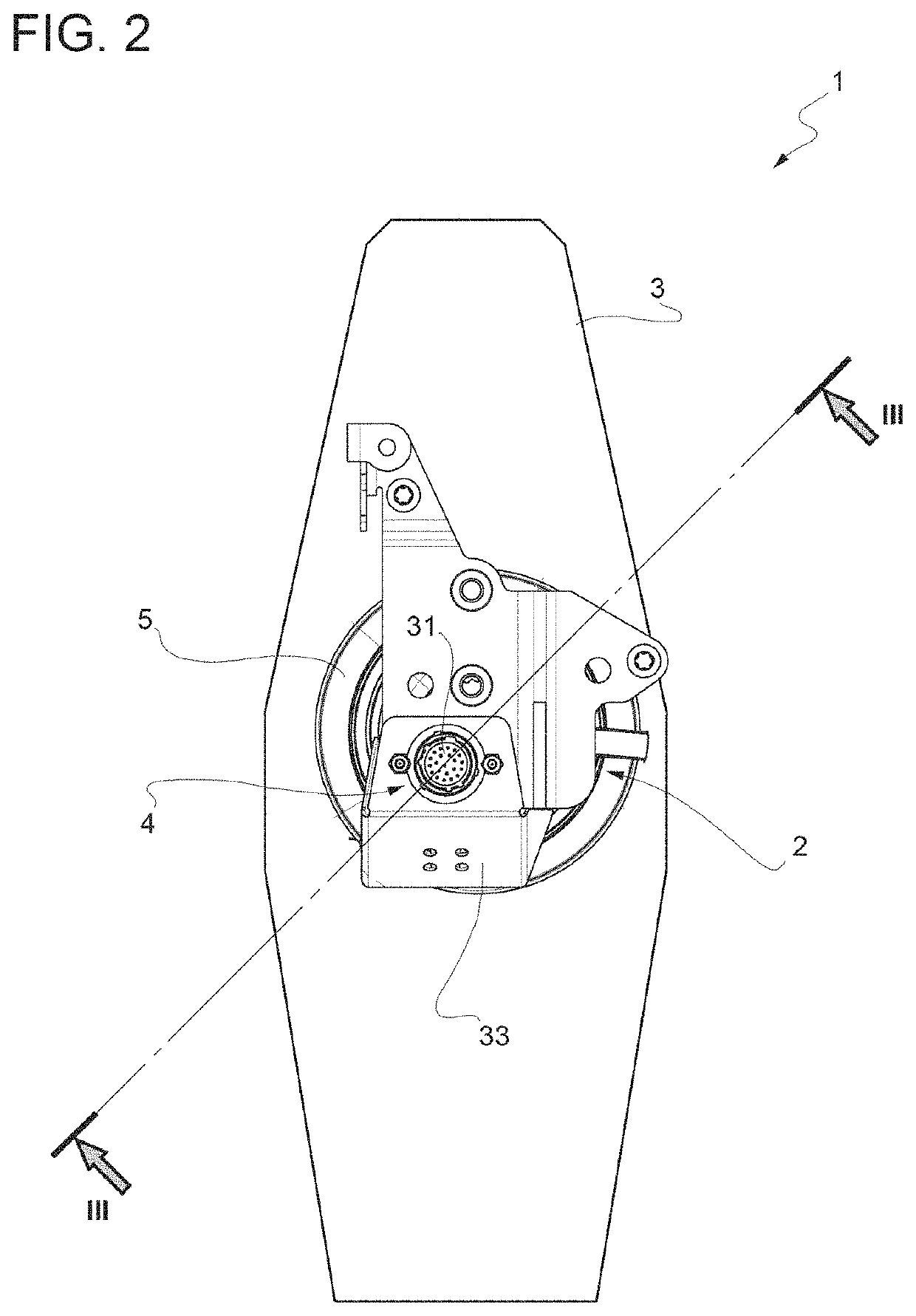
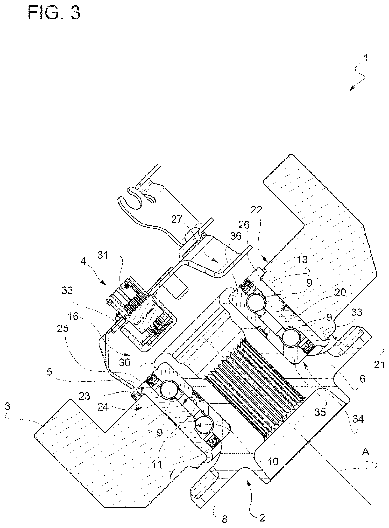
[0013]With reference to FIGS. 1 and 4, in these figures the number 1 indicates the whole of a vehicle suspension assembly, comprising a wheel hub unit 2, a suspension upright or knuckle 3 for the wheel hub unit 2, and a sensorized system 4 generally configured for detecting mechanical stresses acting on the wheel hub unit 2.
[0014]A wheel hub unit 2 comprises a rolling bearing 34 which in turn comprises a radially outer ring 5 and a radially inner ring 35, an annular flanged hub 6 inserted coaxially radially on the inside of the radially outer ring 5 and coupled angularly and integrally to the inner ring ...
PUM
| Property | Measurement | Unit |
|---|---|---|
| mechanical stresses | aaaaa | aaaaa |
| axis of symmetry | aaaaa | aaaaa |
| forces | aaaaa | aaaaa |
Abstract
Description
Claims
Application Information