Coaxial terminal, coaxial connector, wiring board, and electronic component testing apparatus

a technology of coaxial terminals and wiring boards, which is applied in the direction of measuring instruments, coupling device connections, instruments, etc., can solve the problems of not being able to satisfy the desired electrical characteristics, and achieve the effect of maintaining the impedance of the coaxial terminal

Active Publication Date: 2022-10-04
ADVANTEST CORP +1
View PDF27 Cites 0 Cited by
  • Summary
  • Abstract
  • Description
  • Claims
  • Application Information

AI Technical Summary

Benefits of technology

[0006]One or more embodiments of the present disclosure provide a coaxial terminal capable of ensuring desired electrical characteristics while reducing the size, and a coaxial connector, a wiring board, and an electronic component testing apparatus that include the coaxial terminal.
[0016]According to one or more embodiments of the present disclosure, since a part of the first main body of the signal terminal is exposed from the insulating member through the opening and the length L1 of the insulating member and the length L2 of the opening satisfies the relationship of the above formula (1), it is possible to interpose much air that has the relative dielectric constant lower than resin thereof between the signal terminal and the ground terminal. Therefore, in one or more embodiments of the present disclosure, it is possible to maintain the impedance of the coaxial terminal even when the coaxial terminal is miniaturized, and it is possible to ensure the desired electrical characteristics while miniaturizing the coaxial terminal.

Problems solved by technology

On the other hand, if the coaxial terminal is simply miniaturized, there is a case where it is impossible to satisfy the desired electrical characteristics.

Method used


Image

  • Coaxial terminal, coaxial connector, wiring board, and electronic component testing apparatus
  • Coaxial terminal, coaxial connector, wiring board, and electronic component testing apparatus
  • Coaxial terminal, coaxial connector, wiring board, and electronic component testing apparatus

Examples


Embodiment Construction

[0033]Hereinafter, embodiments of the present disclosure will be described with reference to the drawings.

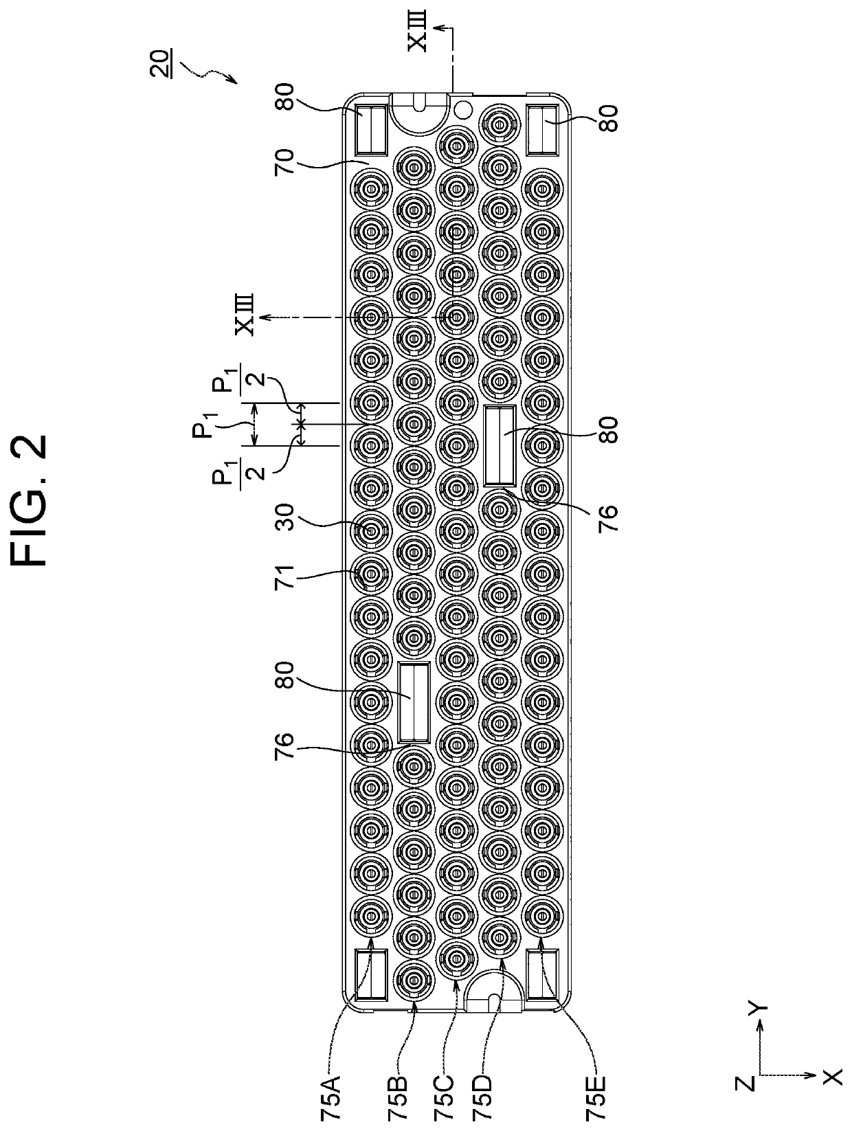
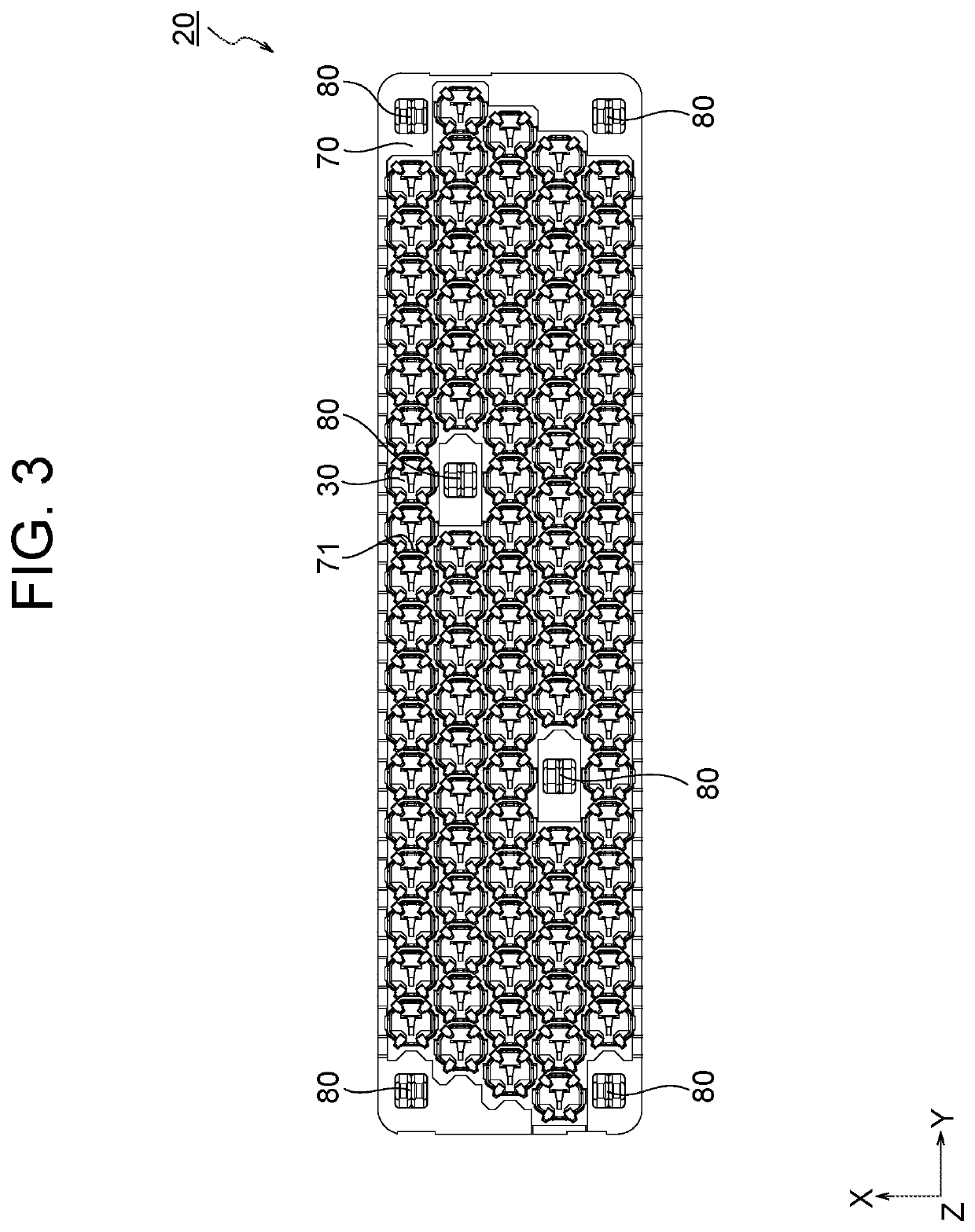
[0034]FIG. 1 is a perspective view showing a wiring board in the present embodiment. FIG. 2 is a plan view of a coaxial connector in the present embodiment, FIG. 3 is a bottom view of the coaxial connector in the present embodiment, FIG. 4 is an exploded perspective view of the coaxial connector in the present embodiment as viewed from below. FIG. 5 is a plan view showing a modification of the coaxial connector in the present embodiment.

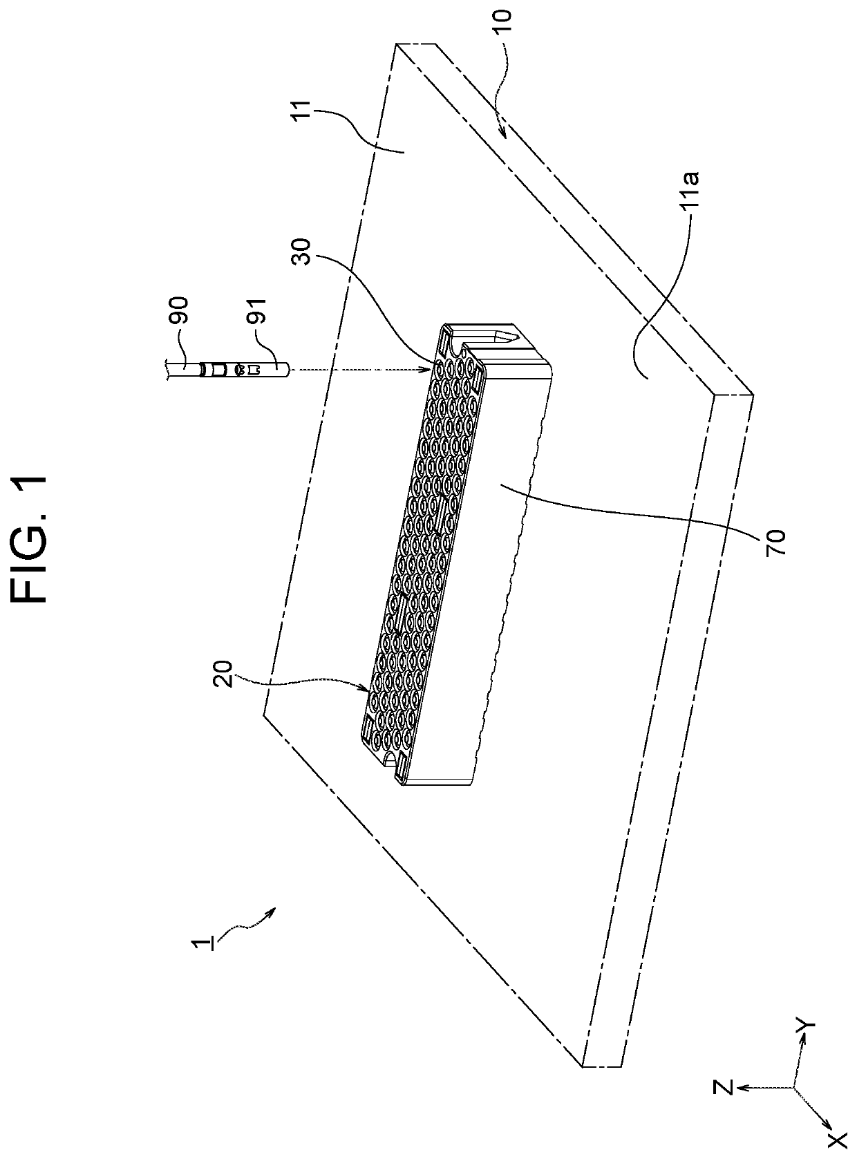
[0035]As shown in FIG. 1 a wiring board 1 in the present embodiment includes a wiring board body 10, and a coaxial connector 20 mounted on the wiring board body 10. As will be described later, the wiring board 1 can be used, for example, as the performance board 120 or the test module 141 of an electronic component testing apparatus 100 (refer to FIG. 16).

[0036]The wiring board body 10 is a printed wiring board that includes an insulating substra...


PUM


Abstract

A coaxial terminal includes a signal terminal, a tubular ground terminal that covers the signal terminal, and an insulating member interposed between the signal terminal and the ground terminal. The signal terminal includes a main body that is covered by the insulating member, an upper contact piece that extends from the main body to +Z direction side, and a lower contact piece that extends from the main body to −Z direction side. The insulating member has an opening through which a part of the main body is exposed. A following formula (1) is satisfied:L2≥½×L1  (1)where L1 is a length of the insulating member along an axial direction of the coaxial terminal, L2 is a length of the opening along the axial direction.

Description

CROSS-REFERENCE TO RELATED APPLICATIONS[0001]The present application claims priority from Japanese Patent Application No. 2020-091493 filed on May 26, 2020, the contents of which are incorporated herein by reference in their entirety.BACKGROUNDTechnical Field[0002]The present disclosure relates to a coaxial terminal that can be used in an electronic component testing apparatus that tests an electronic component to be tested (DUT: Device Under Test) such as a semiconductor integrated circuit element, and a coaxial connector, a wiring board, and an electronic component test apparatus that include the coaxial terminal.Description of the Related Art[0003]A conventional coaxial terminal includes a ground terminal that has a tubular body and a signal terminal that is disposed inside the tubular body, and the ground terminal has a plurality of contact portions that contacts the circuit board (e.g., refer to Patent Document 1).PATENT DOCUMENT[0004]PATENT DOCUMENT 1: JP 2011-238495 A[0005]In...

Claims


Application Information

Patent Timeline
Patent Type & Authority Patents(United States)
IPC IPC(8): H01R13/6471H01R24/50H01R13/40H01R12/71G01R1/04
CPCH01R13/6471G01R1/0416H01R12/714H01R13/40H01R24/50H01R13/652H01R24/38H05K1/181H01R13/6477H01R12/716H01R24/44H01R13/432G01R31/2808H01R9/05
Inventor SESHIMO, TAKAHITOSHIBUYA, ATSUNORIARAI, MASAYUKIOYAMA, MASATAKAAKIYAMA, SHIGERUMATSUMOTO, AYAKO
Owner ADVANTEST CORP
Why Eureka
Try Eureka