
Chair with molded panel

a technology of molded panels and chairs, applied in the field of chairs with molded panels, can solve the problems of increased inventory, increased cost, and areas subject to wear and tear, and achieve the effect of being cheap to manufactur

Active Publication Date: 2022-10-11
SERIES INT
View PDF30 Cites 0 Cited by
  • Summary
  • Abstract
  • Description
  • Claims
  • Application Information

AI Technical Summary

Benefits of technology

The present invention provides a seat that is affordable and customizable while keeping the basic chair structure. The seat has thin / flexible supports across a support frame, with a rigid panel attached to the frame and cushion. The cushion has space for the foam to deflect without interference from the rigid panel. This design allows for premium features like additional shells or rigidity while maintaining comfort. It also allows for a smaller envelope size.

Problems solved by technology

One of the challenges with large seating projects is that each designer or architect will want different design features, depending on the budget and room design.
Similar issues exist with a number of other components.
This creates parts inventory increases and customization increases which leads to increased cost in that a high end wood panel back and seat chair involves a very different process than a less expensive plastic backed chair.
Furthermore, while some situations it may be desirable to have an upholstered rear of the back and / or bottom of the seat, these areas can be subject to wear and tear.
However, the downside of this is that the more comfortable webbing and injection molded foam cannot be used as the whole purpose of that design is to allow the bottom of the seat to flex down to provide added comfort in less thickness.
The hard wood or plastic support would detract from this comfort or alternately will require much more foam, which is more expensive and increases the chair envelope—a feature that can be undesirable given fire code restrictions and free space egress requirements for long rows of chairs in large auditoriums.

Method used


Image

  • Chair with molded panel
  • Chair with molded panel
  • Chair with molded panel

Examples


Embodiment Construction

[0036]Referring now to the drawings, wherein like reference numerals designate corresponding structure throughout the views. The following examples are presented to further illustrate and explain the present invention and should not be taken as limiting in any regard.

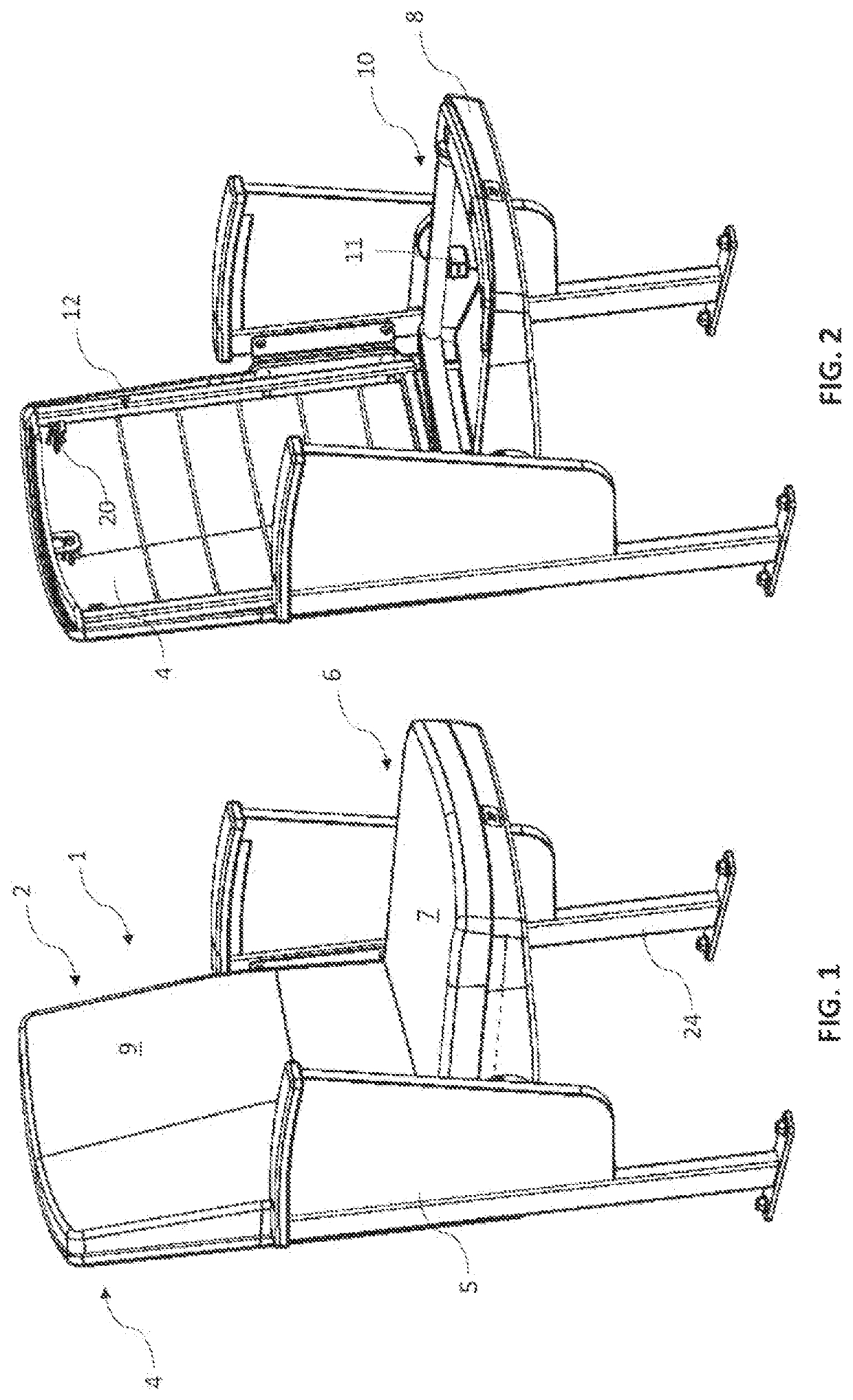
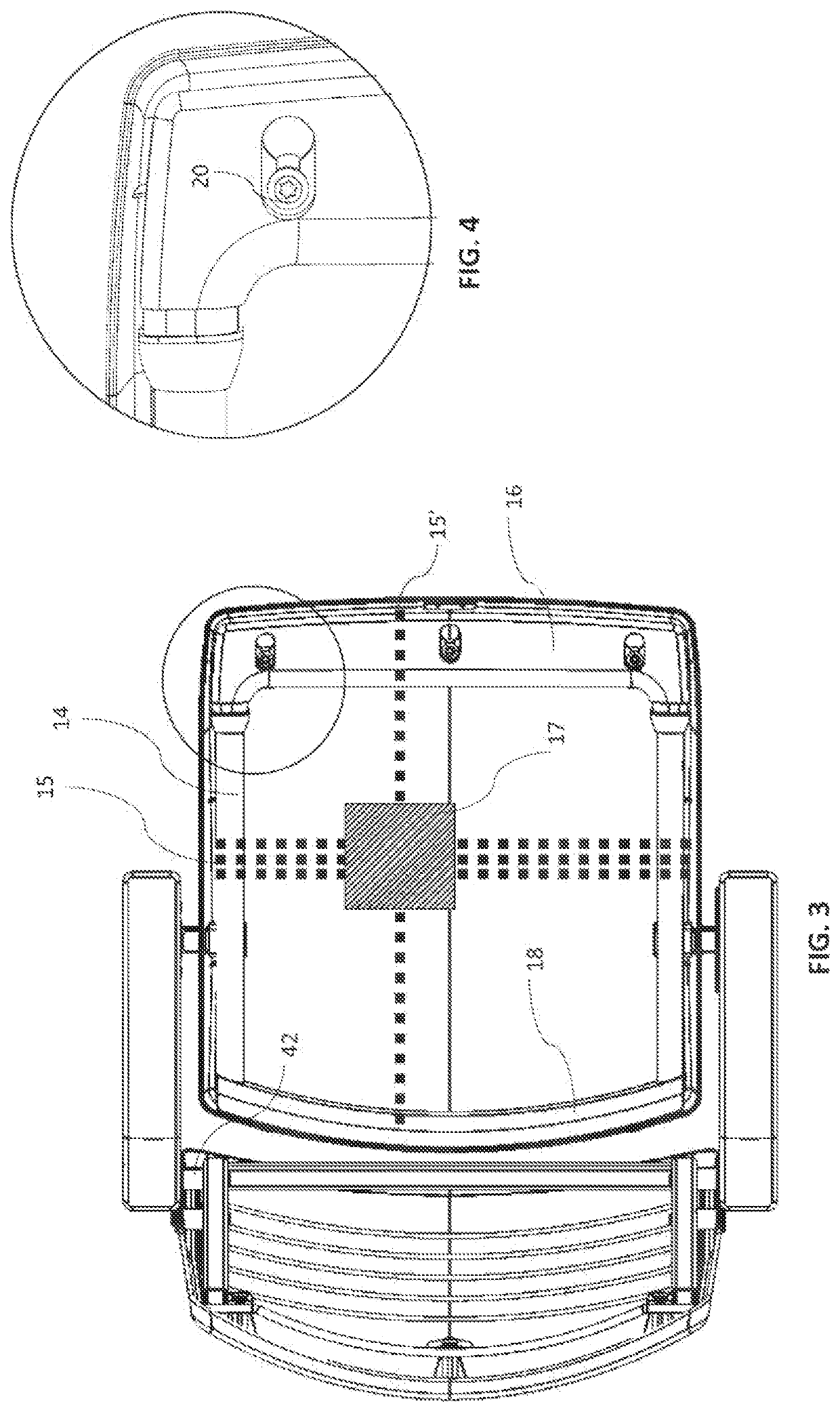
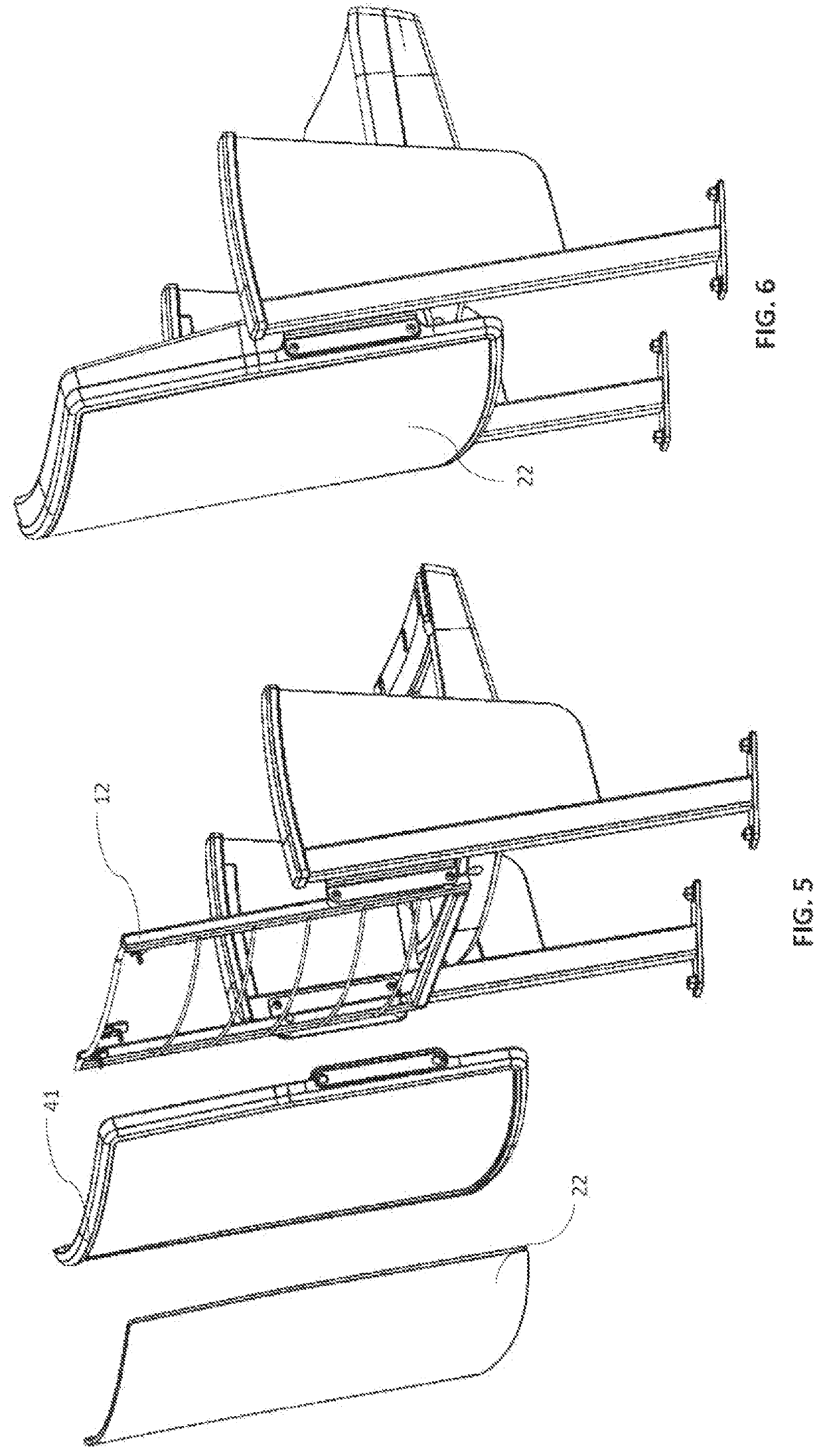
[0037]A chair according to the present invention is shown in FIG. 1 an the following figures. The chair 1 includes a seat 6, a backrest 4 and a frame including e.g. frame pieces 34 / 36 with legs 24 that bolt to a floor / riser or other fixed structure. The back cushion 9 and the seat cushion 7 are upholstered foam and optional side panels 5 can be provided, depending on the aesthetic requirements. FIG. 2 shows the chair of FIG. 1 but with the cushions 7 / 9 removed so that the interior support structure can be seen. The back support 12 provides a metal frame which is molded over in foam. The seat frame 10 is also molded over in foam with both the seat and backrest being further upholstered. Rigid panel 8 is provided to secur...


PUM

PropertyMeasurementUnit
Flexibilityaaaaaaaaaa
Perimeteraaaaaaaaaa

Abstract

A chair is provided with a seat support frame which may be comprised of at least two tubes spaced apart by a polymer connector. The seat support frame supports a foam cushion and the frame may be embedded in the foam and may include flexible supports across the support frame also embedded in the foam. A rigid panel has a cavity and the rigid panel is arranged adjacent an outer surface of said foam cushion with at least part of said foam cushion positioned within the cavity, wherein said rigid panel is affixed to said support frame and an inner surface of said rigid panel faces the outer surface of said foam cushion.

Description

FIELD OF THE INVENTION[0001]The following invention relates to seating and in certain embodiments to seating designed for theaters, auditoriums, meeting rooms, event spaces and / or lecture rooms / halls. In some cases these seats are “fixed” in that they are bolted or otherwise secured to the floor they rest on.BACKGROUND OF THE INVENTION[0002]One of the challenges with large seating projects is that each designer or architect will want different design features, depending on the budget and room design. As a result, many large orders of seats involve a seat being semi-custom designed and then manufactured based on the volume of seats for a particular job.[0003]As a result, each seat with different options will often share some component compatibility, but not others. For example, seats with a wood back or a plastic back or upholstered back often each require different back support pieces which are generally not interchangeable. Similar issues exist with a number of other components. Th...

Claims


Application Information

Patent Timeline
IPC IPC(8): A47C1/121A47C4/06A47C7/16A47C7/24A47C7/18
CPCA47C1/121A47C7/185A47C7/16A47C31/02
Inventor OLARTE, ALVARO MAURICIO
Owner SERIES INT
Learn More