
Window overmold

a technology of window overmolding and window frame, applied in the field of windows, can solve the problems of compromising the function or durability of the window, difficult cutting of glass in these complex shapes and drilling holes, and reducing the efficiency of window cutting, etc., and achieve the effect of substantially reducing or eliminating the disadvantages and problems of vehicle windows made of glass or comprising electrochromic elements

Active Publication Date: 2022-10-11
GENTEX CORP
View PDF15 Cites 0 Cited by
  • Summary
  • Abstract
  • Description
  • Claims
  • Application Information

AI Technical Summary

Benefits of technology

[0004]In accordance with the present disclosure, the disadvantages and problems associated with vehicle windows made of glass or comprising an electrochromic element have been substantially reduced or eliminated.
[0011]The advantages of certain embodiments of the present disclosure include reducing weight by reducing the size of glass pieces needed for a movable window assembly by substituting regions that would otherwise be made of a higher density window with a lower density overmold material. Further, certain embodiments have the technical advantage of producing a window assembly wherein sides of the window and overmold join in a substantially co-planar fashion, reducing or eliminating problems associated with non-linear, movable surfaces. Additionally, certain embodiments have the technical advantage in that the overmold is more easily manufactured or modified into desirable or complex shapes than glass. Further, in some embodiments, the overmold may be formed to provide for holes and housings therein. This is particularly advantageous wherein the window comprises an electro-optic element, as, for example, these elements may not simply have a hole drilled therethrough without compromising the function or durability of the window. Moreover, some embedment's, have the advantage of providing superior contact between the window and the overmold. In particular, embodiments wherein the overmold comprises a notch or a channel, for interfacing with the window, have greatly increased contact area over embodiments without. These embodiments, via contact in additional orientations, also allow for the overmold, when movable, to apply pulling forces not only perpendicular to the window edge, but parallel thereto. These increased surface areas and additional contact orientations may lead to enhanced bonding strength between the window and the overmold, possibly leading to improved durability and mechanical stability of the window assembly. Finally, in some embodiments, the overmold has the advantage of providing an additional layer of protection at fill port of an electro-optic device, thereby minimizing electro-optic media from leaking out and / or air leaking in to the electro-optic chamber, increasing durability of the electro-optic element.

Problems solved by technology

Additionally, they often use thick glass, making them very heavy, and they also have complex cuts for fit.
Further, actuators for raising and lowering the windows often require holes to be drilled therein.
However, cutting glass in these complex shapes and drilling holes therein is difficult—particularly in the instance of electro-optic windows.
Such actions may compromise the function or durability of the window.

Method used


Image

  • Window overmold
  • Window overmold
  • Window overmold

Examples


Embodiment Construction

[0022]Reference will now be made in detail to present embodiments of the invention, examples of which are illustrated in the accompanying drawings. Whenever possible, the same reference numerals will be used throughout the drawings to refer to the same or like parts.

[0023]For the purposes of description herein, the specific devices and processes illustrated in the attached drawings and described in the following specification are exemplary embodiments of the inventive concepts defined in the appended claims. Specific dimensions and other physical characteristics relating the embodiments disclosed herein are not to be considered as limiting, unless the claims expressly state otherwise.

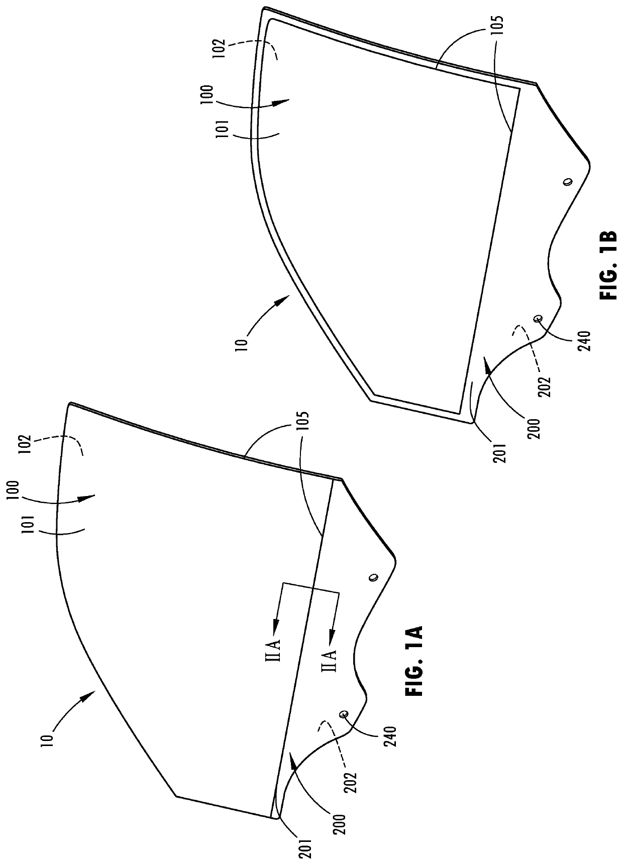
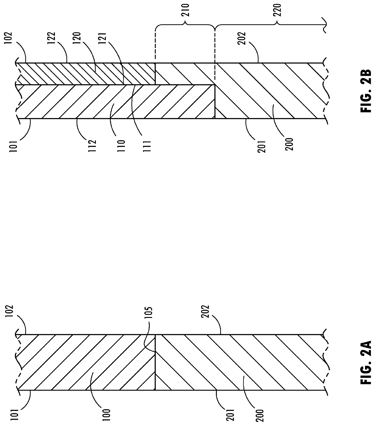
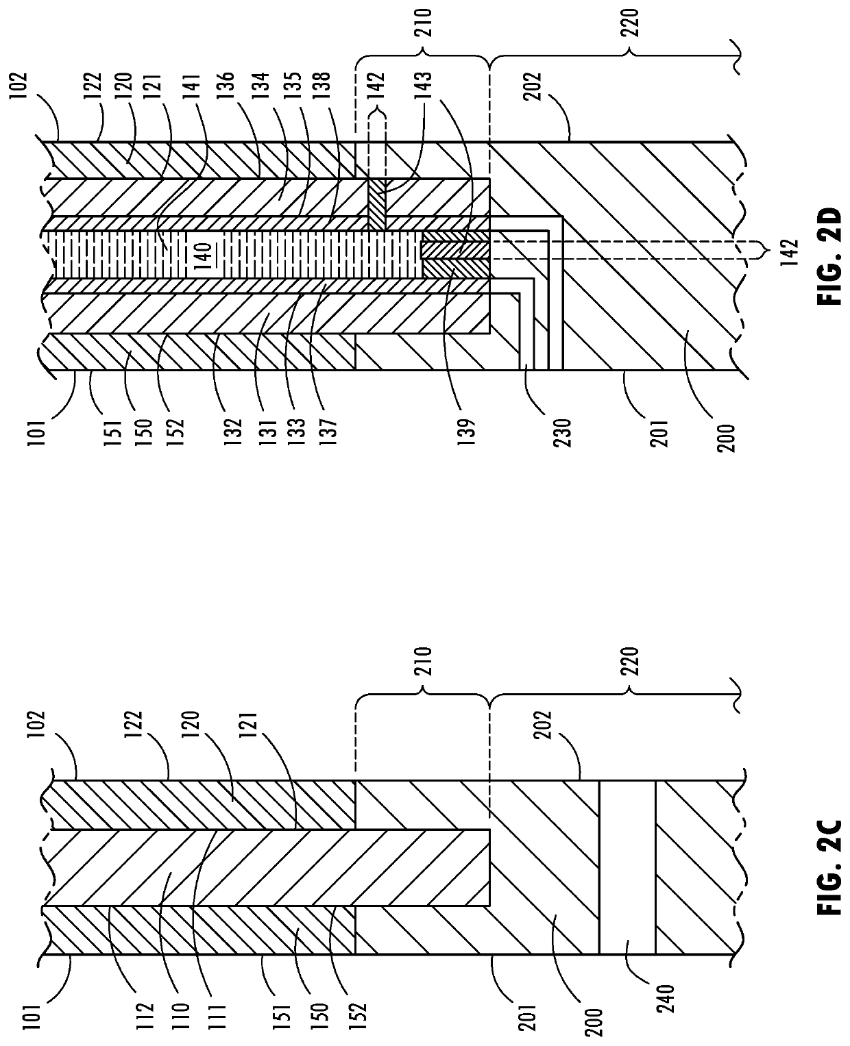
[0024]The present disclosure is directed to improved window assemblies. FIGS. 1a-2f are representations of a window assembly 10. Window assembly 10 may comprise a window 100 and an overmold 200. Further, window assembly 10 may be operable between open and closed positions. Additionally, window assembly ...


PUM

PropertyMeasurementUnit
thicknessaaaaaaaaaa
electrically conductiveaaaaaaaaaa
weightaaaaaaaaaa

Abstract

An overmold is disclosed, wherein the overmold may be incorporated into a window assembly. The overmold comprises a base portion and a receiving portion. The receiving portion may comprise a notch or a channel operable to receive a window. The window may be such that when coupled with the overmold, the sides of the overmold and the window are substantially co-planar. Accordingly, window may comprise a first and a second substrate, wherein the second substrate is coupled to a first side of the first substrate. Further, the first substrate may extend beyond the second substrate. Therefore, the overmold, when in abutting contact with the window, may extend onto the first side of the first substrate up to the second substrate.

Description

CROSS-REFERENCE TO RELATED APPLICATIONS[0001]This application claims priority under 35 U.S.C. § 119(e) to U.S. Provisional Application No. 62 / 949,774 filed on Dec. 18, 2019, entitled “WINDOW OVERMOLD,” the disclosure of which is hereby incorporated by reference in its entirety.FIELD OF INVENTION[0002]The present disclosure is generally related to windows. More particularly, it is related to windows with reduced weight and enhanced modifiability.BACKGROUND OF INVENTION[0003]Windows have been used in vehicles for a long time. These windows, particularly in the context of automobiles, are commonly configured to actuate up and down (i.e. between open and closed positions). Additionally, they often use thick glass, making them very heavy, and they also have complex cuts for fit. Further, actuators for raising and lowering the windows often require holes to be drilled therein. However, cutting glass in these complex shapes and drilling holes therein is difficult—particularly in the instan...

Claims


Application Information

Patent Timeline
Patent Type & Authority Patents(United States)
IPC IPC(8): B60J1/00G02F1/161B60J3/04B60J1/20
CPCB60J1/007B60J1/001B60J1/20B60J3/04G02F1/161B32B17/10036B32B17/10761B32B17/10788
Inventor OVERMYER, NATHAN T.BOMERS, LUKE A.CAMMENGA, DAVID J.
Owner GENTEX CORP
Learn More