Split iron frame door structure
a door structure and iron frame technology, applied in the direction of walls, constructions, building components, etc., can solve the problems of heavy iron frame doors, high transportation costs, inconvenient logistics transportation,
- Summary
- Abstract
- Description
- Claims
- Application Information
AI Technical Summary
Benefits of technology
Problems solved by technology
Method used
Image
Examples
example i
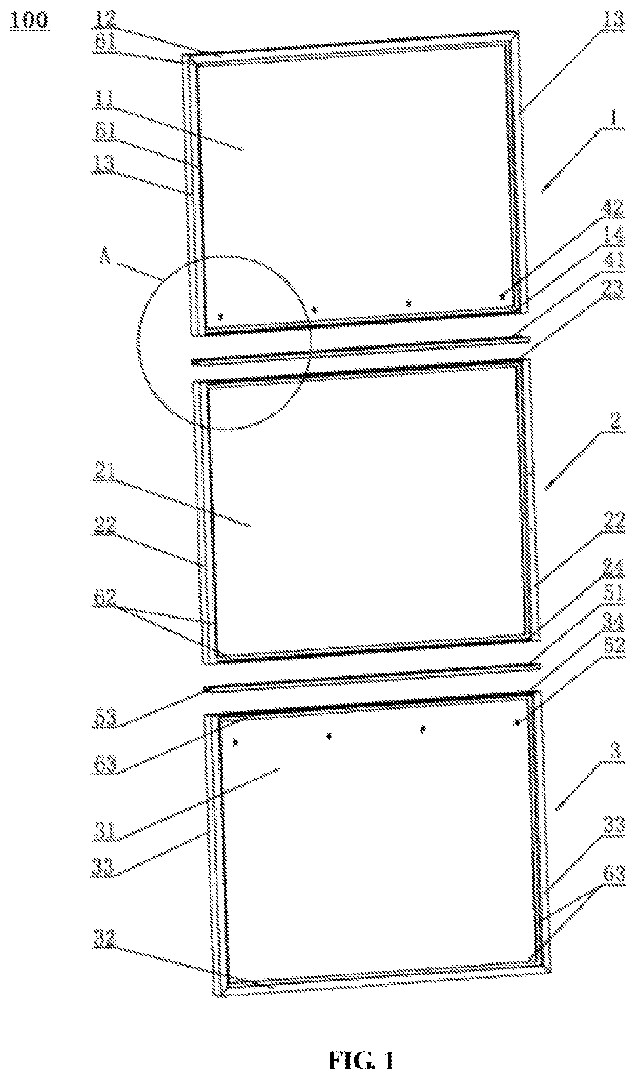
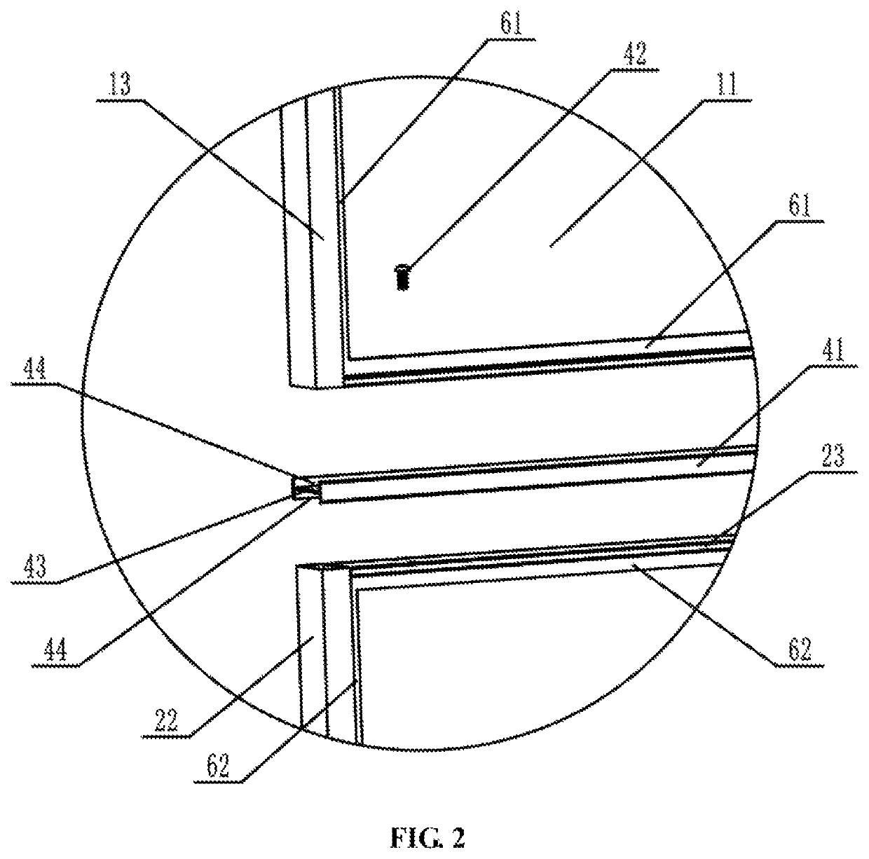
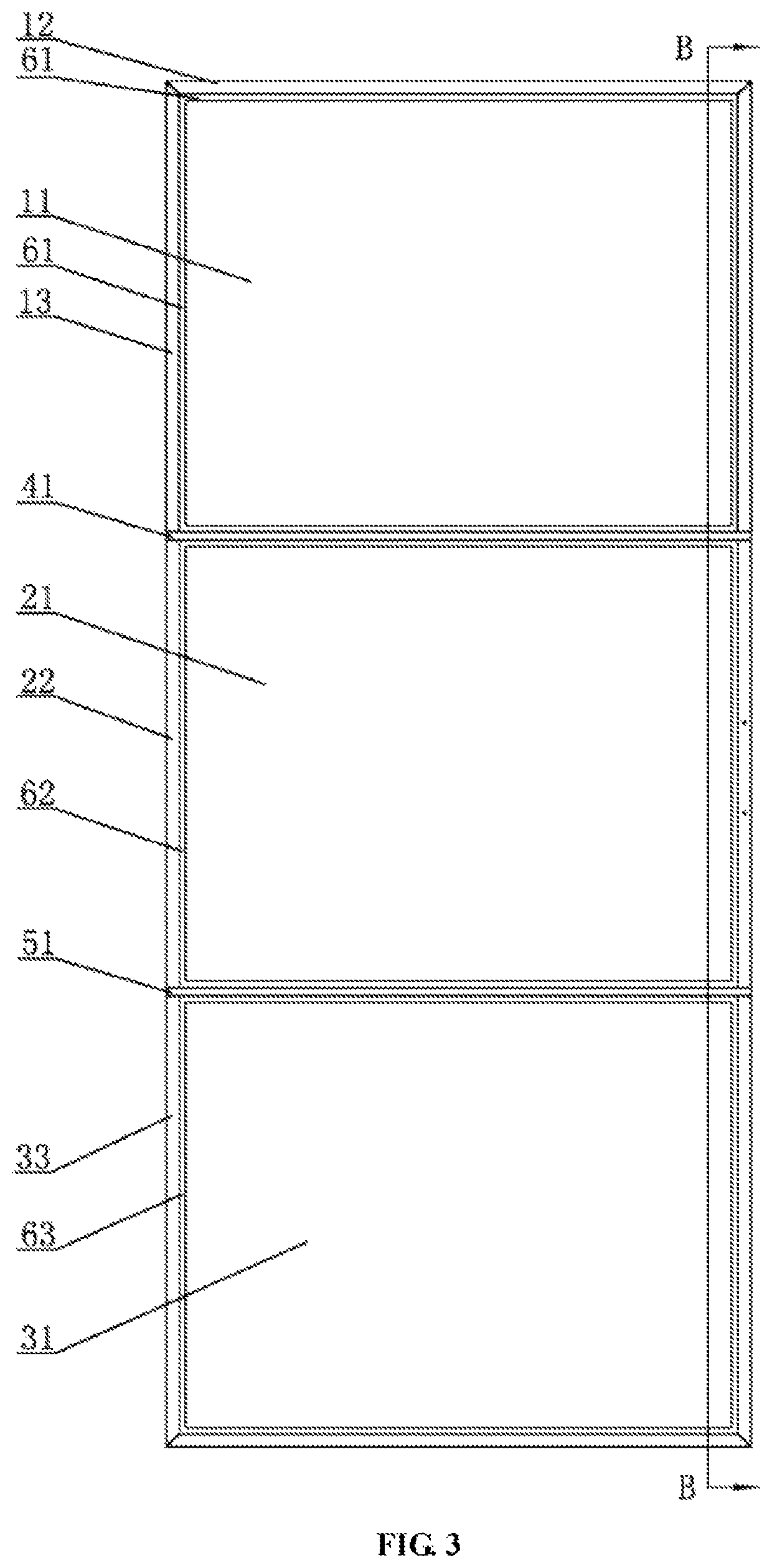
[0044]As shown in FIG. 1 to FIG. 6, the embodiment provides a split iron frame door structure 100, including a top split frame 1, a middle split frame 2 and a bottom split frame 3 which are detachably connected in sequence from top to bottom. The top split frame 1 includes two first side edge frames 13, top glass 11, and a top edge frame 12 which are connected as a whole. The middle split frame 2 includes two second side edge frames 22 and middle glass 21 which are connected as a whole. The bottom split frame 3 includes two third side edge frames 33, bottom glass 31, and a bottom edge frame 32 which are connected as a whole. The top edge frame 12 and the two first side edge frames 13 of the top split frame 1, the two second side edge frames 22 of the middle split frame 2, and the bottom edge frame 32 and the two third side edge frames 33 of the bottom split frame 3 are thin-wall square tube frames. A transversely-arranged first flat-iron edge frame 14 is fixed to the bottom of the t...
example ii
[0046]As shown in FIG. 7 to FIG. 9, the difference between the second example and the first example is as follows. In the second example, the top edge frame 12 and the two first side edge frames 13 of the top split frame 1 as well as the first flat-iron edge frame 14 are each fixed with two first flat-iron division bars 61, which are arranged at intervals and are configured for embedding and fixing the top glass 11. The two second side edge frames 22 of the middle split frame 2, the second flat-iron edge frame 23 and the third flat-iron edge frame 24 are each fixed with two second flat-iron division bars 62, which are arranged at intervals and configured for embedding and fixing the middle glass 21. The bottom edge frame 32 and the two third side edge frames 33 of the bottom split frame 3 as well as the fourth flat-iron edge frame 34 are each fixed with two third flat-iron division bars 63, which are arranged at intervals and configured for embedding and fixing the bottom glass 31.
example iii
[0047]As shown in FIG. 10, the difference between the third example and the second example is as follows. In the third example, the top edge frame 12 of the top split frame 1 is fixedly connected with two trolley plates 71. Each trolley plate 71 is installed with a pulley 72. The pulley 72 is slidably erected on a guide rail 73. The guide rail 73 is fixed to a wall. A door handle 25 is installed on one of the second side edge frames 22 of the middle split frame 2. And a swing stopping device 35 is installed on the bottom edge frame 32 of the bottom split frame 3. The split iron frame door structure 100 in the third example is specifically applied to sliding door systems, and the effect after the split iron frame door structure is installed is as shown in FIG. 10.
PUM
 Abstract
Description
Claims
Application Information
 - R&D
- Intellectual Property
- Life Sciences
- Materials
- Tech Scout
- Unparalleled Data Quality
- Higher Quality Content
- 60% Fewer Hallucinations
Browse by: Latest US Patents, China's latest patents, Technical Efficacy Thesaurus, Application Domain, Technology Topic, Popular Technical Reports.
© 2025 PatSnap. All rights reserved.Legal|Privacy policy|Modern Slavery Act Transparency Statement|Sitemap|About US| Contact US: help@patsnap.com


