
System and method for robust touch detection for on-skin augmented reality/virtual reality interfaces

a virtual reality and touch detection technology, applied in the field of system and method for robust touch detection for on-skin augmented reality/virtual reality interfaces, can solve the problems of inability to detect the touch, the user must take extra care, and the approach is invasive, and achieves high accuracy tracking, simple instrumentation, and robust touch segmentation

Active Publication Date: 2022-10-11
CARNEGIE MELLON UNIV
View PDF2 Cites 0 Cited by
  • Summary
  • Abstract
  • Description
  • Claims
  • Application Information

AI Technical Summary

Benefits of technology

The system achieves high accuracy and precision in touch detection, reducing hover ambiguity and enabling intuitive, comfortable interactions with a high touch segmentation accuracy of 93.8% and mean distance error of 5.3 mm, supporting fine-grained interactions without the need for expensive hardware.

Problems solved by technology

Both of these approaches excel at fluid, coarse-grained input but are weaker at fine-grained interactions, such as typing on a virtual keyboard.
Indeed, it is rare to see closely packed targets in current AR / VR interfaces, and when they do appear, extra care must be taken by the user.
One option is to directly modify the body, for example, by adding a sensing layer to the skin's surface or implanting sensors under the skin, though this approach is invasive and not all users are comfortable with such instrumentation.
Drawbacks of these types of optical systems include the need to use markers or being limited to only finger-to-finger touches.
This arrangement requires both hands to be instrumented and does not consider integration into AR / VR headsets.
However, a common weakness across camera-based systems is the inability to accurately segment true touches from fingers hovering just above the skin as cameras often lack sufficient resolution or the field of view necessary to detect touches as opposed to hovering.
This hover ambiguity makes end user touch interactions more cumbersome, with users often having to perform exaggerated (z-axis) trajectories to compensate.

Method used


Image

  • System and method for robust touch detection for on-skin augmented reality/virtual reality interfaces
  • System and method for robust touch detection for on-skin augmented reality/virtual reality interfaces
  • System and method for robust touch detection for on-skin augmented reality/virtual reality interfaces

Examples


Embodiment Construction

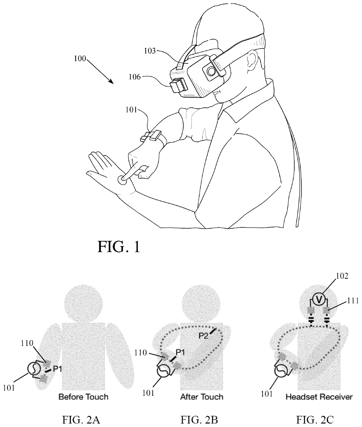
[0021]The system and method of the present invention leverage the conductivity of the human body, which serves as a transmission medium for radio frequency (RF) signals. In one embodiment, the augmented reality / virtual reality (AR / VR) interface 100 comprises an emitter 101 and a receiver 102. As shown in FIG. 1, the emitter 101 can be a smartwatch or similar body-worn device and comprises two electrodes 110 used to transmit the signal into the user's body. The receiver 102 is housed within a AR / VR headset 103 and is capable of detecting the signal from the emitter 101.

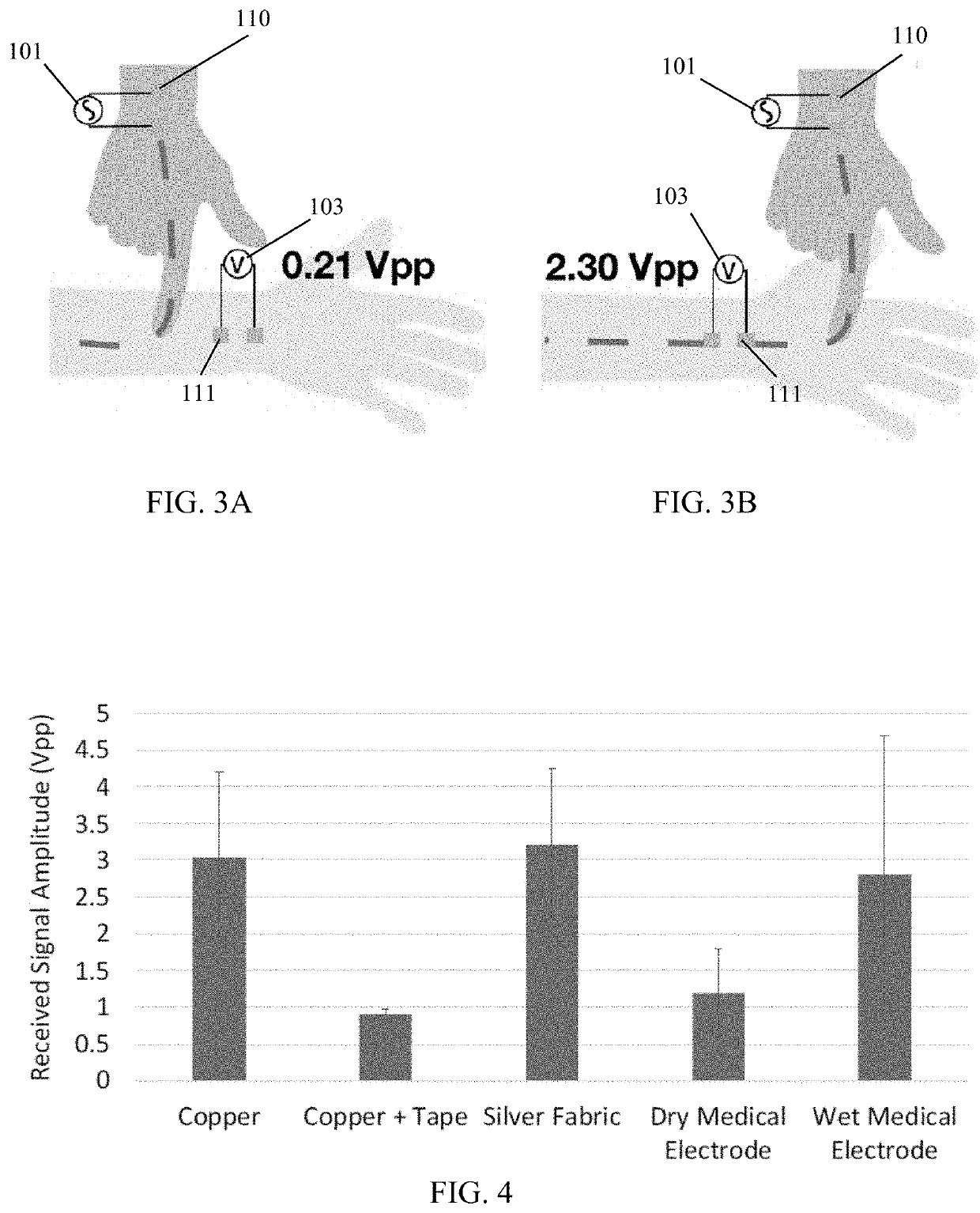
[0022]When a user wears an emitter 101 on the arm, wrist, hand, or other body part, the RF signal is conducted through the user's skin on a short path (P1) between the electrodes 110 of the emitter 101, as shown in FIG. 2A. When a user touches their arm or hand, a second, longer path (P2) is formed through the opposite arm from which the emitter 101 is worn. Path P2 is depicted on FIG. 2B. Thus, the RF signal emitted f...


PUM


Abstract

A system and method for detecting when a user contacts one arm to an opposing arm. The system comprises an emitter worn by the user on one arm and a receiver located on an opposing arm, on the user's head, or on a different part of the user's body. Contact, or touch, is indicated by comparing the value of an electrical signal flowing along a path establish, in part, through the user's skin to a threshold. When touch is initiated, multiple electrical paths are created, including one that generates airborne signal emanating from the user's body.

Description

CROSS-REFERENCE TO RELATED APPLICATIONS[0001]This application claims the benefit under 35 U.S.C. § 119 of Provisional Application Ser. No. 62 / 973,569, filed on Oct. 11, 2019, which is incorporated herein by reference.STATEMENT REGARDING FEDERALLY SPONSORED RESEARCH[0002]Not applicable.BACKGROUND OF THE INVENTION[0003]Augmented reality and virtual reality (AR / VR) systems generally rely on either handheld controllers or in-air bare hand gestures for user input. Both of these approaches excel at fluid, coarse-grained input but are weaker at fine-grained interactions, such as typing on a virtual keyboard. Indeed, it is rare to see closely packed targets in current AR / VR interfaces, and when they do appear, extra care must be taken by the user.[0004]Other modalities are possible, which can improve the precision, bandwidth, and comfort of AR / VR interactions. One option is to directly modify the body, for example, by adding a sensing layer to the skin's surface or implanting sensors under ...

Claims


Application Information

Patent Timeline
Patent Type & Authority Patents(United States)
IPC IPC(8): G06F3/01
CPCG06F3/015G06F3/011G06F3/014
Inventor ZHANG, YANGHARRISON, CHRISTOPHER
Owner CARNEGIE MELLON UNIV
Learn More