Aerosol generating device with spiral movement for heating

Active Publication Date: 2022-10-25
PHILIP MORRIS PROD SA
View PDF23 Cites 0 Cited by
  • Summary
  • Abstract
  • Description
  • Claims
  • Application Information

AI Technical Summary

Benefits of technology

[0009]Various aspects or embodiments of the aerosol generating devices described herein may provide one or more advantages relative to currently available or previously described aerosol generating devices. For example, one or more aerosol generating devices described herein may use a relatively small heating element, which may provide space and energy efficiency. By using a small heating element, the amount of energy required to heat the element to a sufficient temperature to cause aerosol generation may be reduced relative to devices employing larger heating elements. In addition, the use of a smaller heating element may allow for heating of a smaller portion of the article containing the aerosol generating substrate, which may reduce wasteful depletion of the substrate. That is, targeted heating of the substrate preferably depletes only a portion of the substrate s

Problems solved by technology

Because the substrate is not combusted, by-products of combustion and pyrolysis are

Method used


Image

  • Aerosol generating device with spiral movement for heating
  • Aerosol generating device with spiral movement for heating
  • Aerosol generating device with spiral movement for heating

Examples


Embodiment Construction

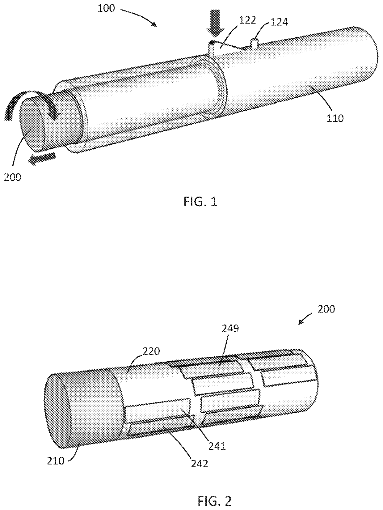
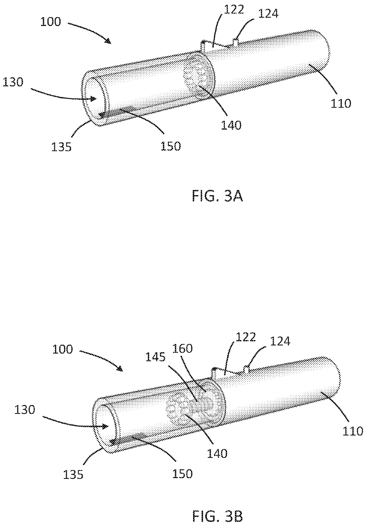
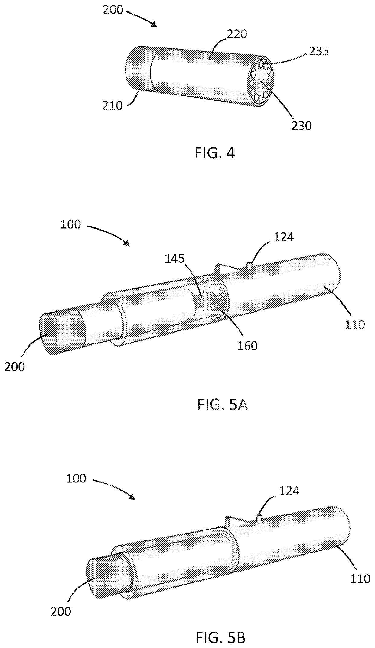
[0020]An aerosol generating device according to an aspect of the present invention comprises a housing having an open end and forms a cavity in communication with the open end. A consumable aerosol generating article, such as a rod-shaped article, may be inserted into the cavity through the open end of the device. A portion of the article may protrude from the open end of the cavity and may serve as a mouthpiece, through which a user may inhale generated aerosol.

[0021]The device comprises a heating element in, or exposed to, the cavity. When the article is inserted in the cavity, the heating element is positioned adjacent to the article and may heat aerosol generating substrate of the article to cause generation of an aerosol, that may be inhaled through the mouth end of the article by a user. The heating element may be positioned adjacent the aerosol generating article and may heat the aerosol generating substrate from outside the article. The heating element may be in direct conta...


PUM


Abstract

An aerosol generating device includes a housing having an open end and forms a cavity in communication with the open end for receiving an aerosol generating article. The device further includes a rotatable capture element disposed in the cavity. The rotatable capture element is operable to retain the aerosol generating article within the cavity. The rotatable capture element is longitudinally movable within the cavity. The device further includes a heating element in communication with the cavity. The heating element is operable to heat the aerosol generating article retained by the capture element within the cavity. Combined rotation and longitudinal movement of the capture element causes the aerosol generating element to spiral relative to the heating element.

Description

RELATED APPLICATIONS[0001]This application is the § 371 U.S. National Stage of International Application No. PCT / IB2018 / 055358, filed 18 Jul. 2018, which claims the benefit of European Application No. 17182691.0, filed 21 Jul. 2017.INTRODUCTION[0002]The present disclosure relates to aerosol generating devices for use with aerosol generating articles having an aerosol generating substrate, or “consumable”, such as a tobacco substrate. Preferably, such a device is configured to sufficiently heat the substrate to cause generation of an aerosol, without combusting the substrate. These are known as “heat-not-burn” devices.[0003]A consumable comprising an aerosol generating substrate may be heated in a number of suitable ways to cause aerosol generation. The devices may contain a single heater or multiple heaters. The use of a single heater may be advantageous because it may require less space and may allow the device to be smaller. The device may also be less expensive to produce and eas...

Claims


Application Information

Patent Timeline
IPC IPC(8): A24F40/46A61M11/04A24D1/20A24F40/40A24F40/60H05B3/42A24F40/20
CPCA61M11/042A24D1/20A24F40/40A24F40/46A24F40/60H05B3/42A24F40/20A61M15/06A61M2205/103A61M2205/106A61M2205/3368A61M2205/8206A61M15/005H05B6/108A24F40/00A24F47/00
Inventor REEVELL, TONY
Owner PHILIP MORRIS PROD SA
Why Eureka
Try Eureka