Fluorescence photometer and observation method

a fluorescence photometer and fluorescence wavelength technology, applied in the field of fluorescence photometers, can solve the problems of limited sample size that can be observed, difficult to check the emission distribution, and difficulty in detecting the emission intensity,

Active Publication Date: 2022-11-01
HITACHI HIGH TECH SCI CORP
View PDF22 Cites 2 Cited by
  • Summary
  • Abstract
  • Description
  • Claims
  • Application Information

AI Technical Summary

Benefits of technology

[0016]The present disclosure provides a fluorescence photometer and an observation method that are capable of observing a sample of any size and of reducing an observation time.
[0023]According to the present disclosure, it is possible to obtain, at the same time, a spectrum and an image for the same observation target area of a sample by guiding excitation light that is separated into monochromatic light by an excitation-side spectroscope to the sample through an excitation light-guiding member, guiding light emitted from the sample to a fluorescence-side spectroscope through a fluorescent light-guiding member, and directly detecting the lights of respective wavelengths with a detector. In addition, with the use of the light-guiding member comprised of the excitation light-guiding member and the fluorescent light-guiding member, it is possible to acquire a spectrum and an image of an arbitrary target region of a sample having an arbitrary size.

Problems solved by technology

In this case, since a sample chamber to accommodate a sample needs to be a dark room, it is difficult to check an emission distribution, an emission color, emission intensity, and the like in a fluorescence surface of the sample when the sample is irradiated with excitation light.
In addition, the sample size that can be observed is restricted by the size of the sample stage of a microscope.
In addition, in the case of the fluorescence side, since only intensity information can be obtained from an image generated based on light having passed through the optical filters by a CCD camera, fluorescence wavelengths are limited to the number of optical filters provided on the fluorescence side.
Therefore, it is necessary to take measures such as narrowing down the wavelength range necessary for analysis, and obtained information is limited.
In addition, the apparatus performs an operation of simply calculating a reflection spectrum from an image signal but does not perform an operation of acquiring a fluorescence spectrum as an observed measurement value.
However, since the fluorescence spectrum is calculated from an image, the resolution of data and the wavelength interval are restricted.

Method used


Image

  • Fluorescence photometer and observation method
  • Fluorescence photometer and observation method
  • Fluorescence photometer and observation method

Examples


Embodiment Construction

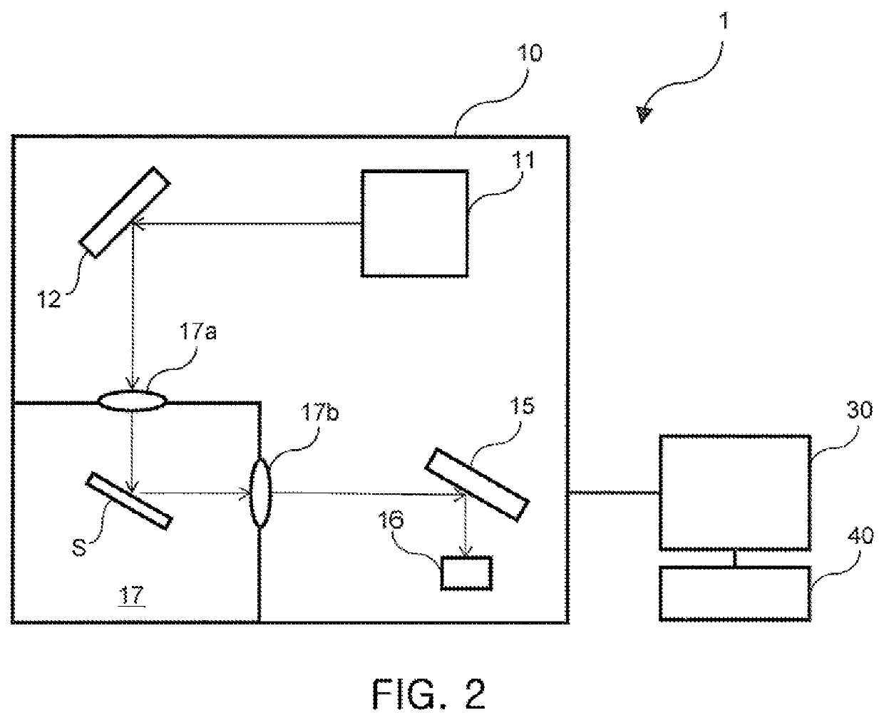
[0034]Hereinafter, specific embodiments of a fluorescence photometer according to the present disclosure will be described in detail with reference to the accompanying drawings. FIGS. 1 and 2 illustrate embodiments of the fluorescence photometerdisclosure to which the present disclosure is applied.

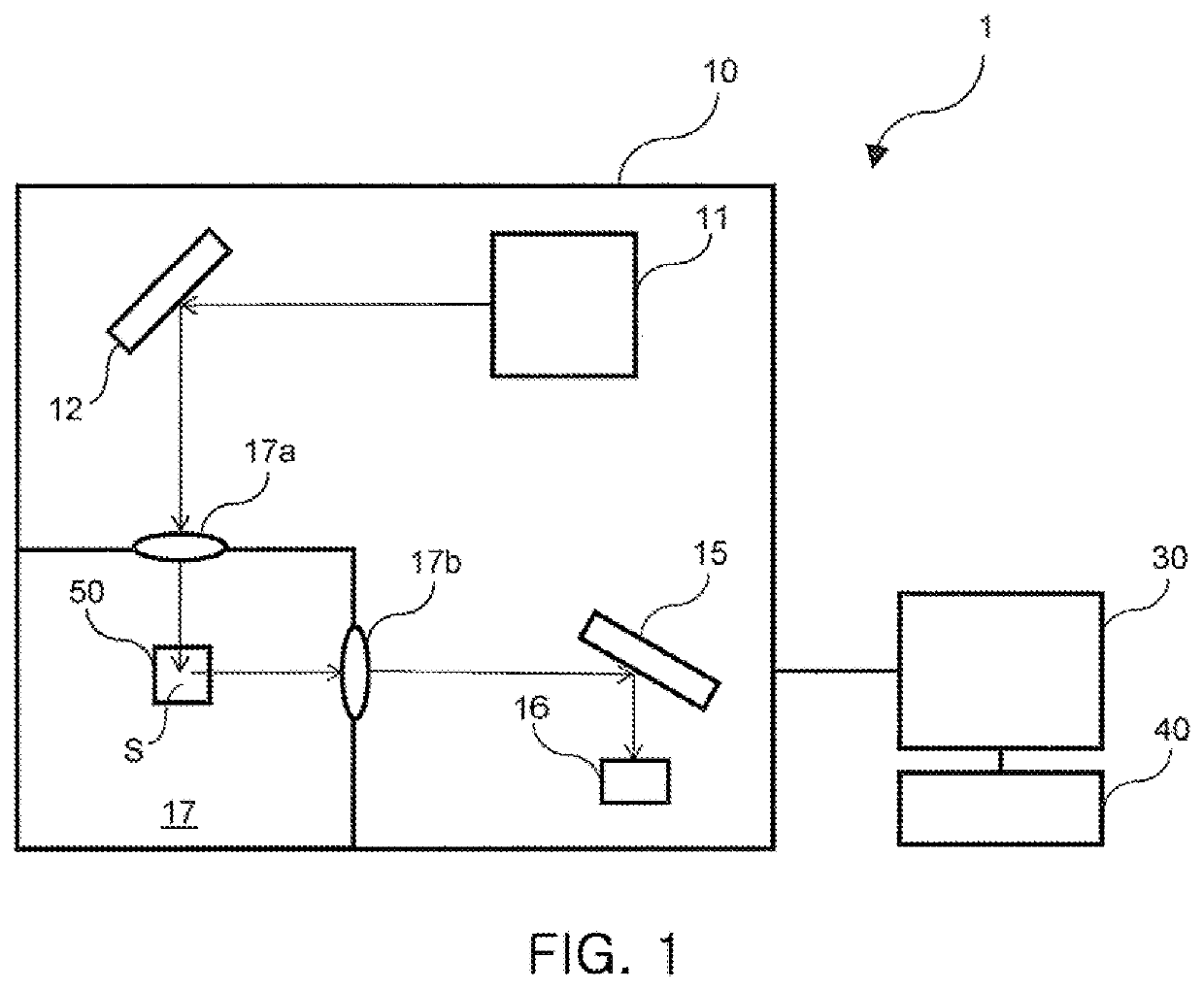
[0035]A fluorescence photometer 1 illustrated in FIG. 1 is an apparatus for irradiating a sample with excitation light and measuring fluorescent light generated from the sample. The fluorescence photometer 1 includes a photometer unit 10, a data processing unit 30 that controls the photometer unit 10 and analyzes the sample, and an operation unit 40 that performs an input operation and an output operation.

[0036]The photometer unit 10 includes a light source 11 that emits continuous light, an excitation-side spectroscope 12 that separates the light emitted from the light source 11 to generate excitation light, a fluorescence-side spectroscope 15 that separates fluorescent light emitted from...


PUM

PropertyMeasurementUnit
areaaaaaaaaaaa
angleaaaaaaaaaa
excitation wavelength EXaaaaaaaaaa

Abstract

A fluorescence photometer includes a photometer unit and an optical fiber unit. The photometer unit includes a light source, an excitation-side spectroscope for separating light emitted from the light source to generate excitation light, and a fluorescence-side spectroscope for separating fluorescent light emitted from a sample irradiated with the excitation light to generate monochromatic light. The optical fiber unit guides the excitation light to the sample placed outside the photometer unit and guides the fluorescent light emitted from the sample to the photometer unit and includes an image fiber for capturing an image of the sample, an excitation-side fiber arranged around the image fiber and for guiding the excitation light to the sample, and a fluorescence-side fiber arranged around the image fiber and to guide the fluorescent light emitted from the sample to the photometer unit. The excitation-side fiber and the fluorescence-side fiber are arranged to surround the image fiber.

Description

CROSS REFERENCE TO RELATED APPLICATION(S)[0001]This application claims the benefit of Japanese Patent Application No. 2019-044976, filed Mar. 12, 2019, which is hereby incorporated by reference in its entirety into this application.BACKGROUND OF THE INVENTION1. Technical Field[0002]The present disclosure relates to a fluorescence photometer and a method of observing a sample with the fluorescence photometer.2. Description of the Related Art[0003]A fluorescence photometer is an apparatus for identifying substances contained in a sample by irradiating the sample with excitation light and measuring fluorescent light generated from the sample. That is, a fluorescence photometer irradiates a sample with excitation light, separates fluorescent light emitted from the sample, and obtains spectral data such as an excitation spectrum, a fluorescence spectrum, a time change, and a three-dimensional fluorescence spectrum. Excitation light is incident on a predetermined area which is typically a...

Claims


Application Information

Patent Timeline
Patent Type & Authority Patents(United States)
IPC IPC(8): G01N21/64G01J3/44
CPCG01N21/64G01J3/4406G01N2021/6417G01N2201/0694G01N21/6456G01N2021/6484G01N2201/0833G01N2021/6423G01J3/10G01J3/0218
Inventor HORIGOME, JUNMARUYAMA, KAIKURITA, KOJISAKAMOTO, HIDEYUKINAKAJIMA, RINOSUZUKI, NAOKI
Owner HITACHI HIGH TECH SCI CORP
Why Eureka
Try Eureka