Terminal connecting structure

a technology of connecting structure and terminal, which is applied in the direction of connecting contact member material, multi-conductor cable end pieces, transportation and packaging, etc., can solve the problems of unstable conductive connection between aluminum electric wires and terminals after crimping, and achieve the effect of improving conductivity between electric wires and terminals and avoiding the influence of crimping

Active Publication Date: 2022-11-01
YAZAKI CORP
View PDF23 Cites 0 Cited by
  • Summary
  • Abstract
  • Description
  • Claims
  • Application Information

AI Technical Summary

Benefits of technology

[0006]An objective of the present invention is to provide a terminal connecting structure which may enable the conductivity to be improved.
[0010]The invention according to claim 1 additionally provides the conductive connection body, wherein one end of the connection body is butt-connected to the aluminum conductor, and another end of the connection body is connected to the terminal via crimping. This enables the terminal to be connected to the electric wire via the connection body without crimping the crimped section to the bundle of cores as conventionally. This may eliminate influence of crimping on the aluminum conductor and enable the conductivity between the electric wire and the terminal to be improved.

Problems solved by technology

However, in a conventional connecting structure, the bundle of cores is crimped by the terminal to connect the aluminum electric wires to the terminal, whereby crimping may cause the conductor cores forming the bundle of cores to be separated from each other to generate a gap between the conductor cores, so that an oxide coating may be formed on surfaces of the conductor cores, and thereby, the conductive connection between the aluminum electric wires and the terminals may be unstable after crimping.

Method used


Image

  • Terminal connecting structure
  • Terminal connecting structure
  • Terminal connecting structure

Examples


Embodiment Construction

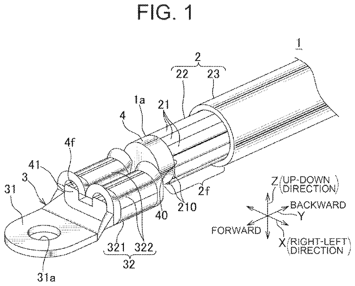
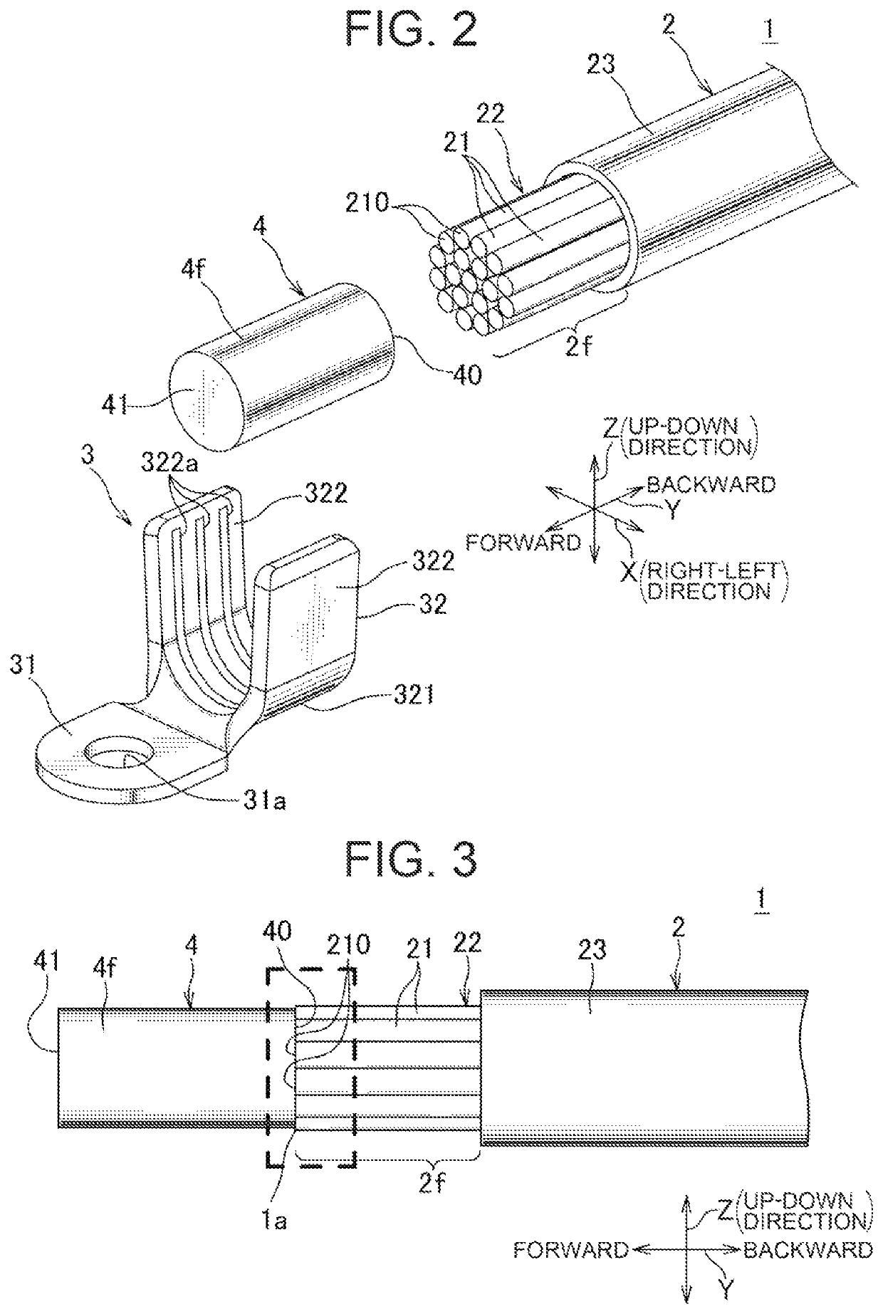
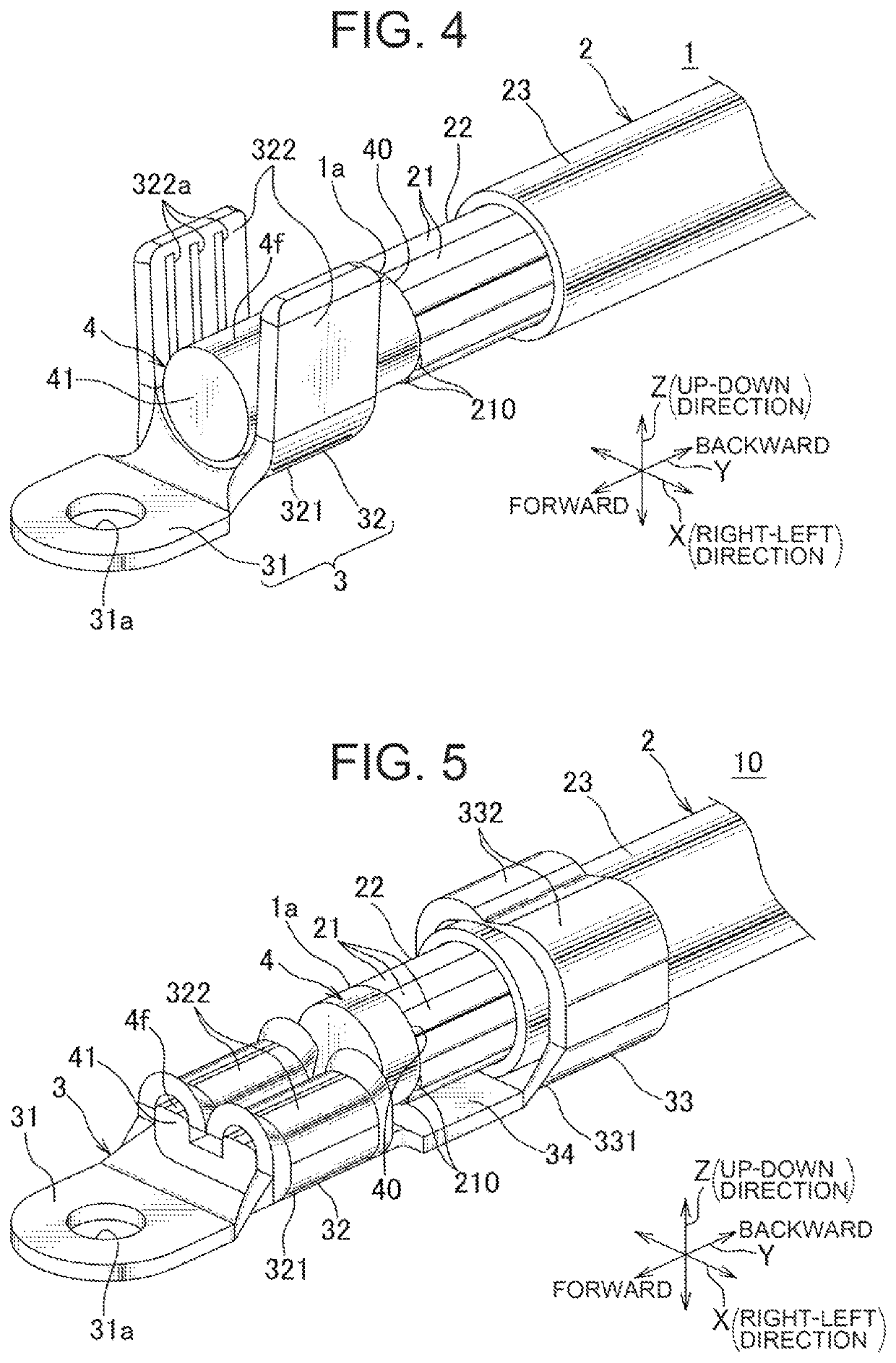
[0016]Hereinafter, an embodiment of the present invention will be described with reference to FIGS. 1 to 4. FIG. 1 shows a perspective view of an electric wire with a terminal according to an embodiment of the present invention. For the electric wire with the terminal 1 according to the present embodiment, a terminal connecting structure according to the present invention is applied, wherein the electric wire 1 constitutes a wire harness to be arranged e.g. in an automobile.

[0017]As shown in FIG. 1, the electric wire 1 includes a coated electric wire 2 (hereinafter referred to as “electric wire 2”), the terminal 3, and a connection body 4 for connecting the electric wire 2 to the terminal 3. According to the present embodiment, a direction in which the electric wire 2 and the connection body 4 are aligned is designated by an arrow Y, a direction (up-down direction) orthogonal to (intersecting) the arrow Y is designated by an arrow Z, and a direction (right-left direction) orthogonal...


PUM


Abstract

An objective of the present invention is to provide a terminal connecting structure which may enable the conductivity to be improved. A terminal connecting structure is intended for connecting a terminal to an electric wire, the electric wire including an aluminum conductor with aluminum, wherein the terminal connecting structure further comprises a conductive connection body formed with aluminum, wherein one end of the connection body is butt-connected to the aluminum conductor, and wherein another end of the connection body is connected to the terminal via crimping. This enables the terminal to be connected to the electric wire via the connection body without crimping the bundle of cores. This may eliminate influence of crimping on the aluminum conductor and enable the conductivity between the electric wire and the terminal to be improved.

Description

BACKGROUND OF THE INVENTIONTechnical Field[0001]The present invention relates to a terminal connecting structure.Background Art[0002]An automobile is equipped with various types of electronic devices, wherein wire harnesses are arranged therein in order to transfer e.g. electric power and / or control signals to such electronic devices. A wire harness includes a plurality of electric wires and a connector, wherein the wire harness is connected to an electronic device or another wire harness by mating this connector to a connector of the electronic device or of the other wire harness.[0003]For electric wires for forming such a wire harness, aluminum may be used as material for conductor cores. As a connecting structure for connecting a terminal to the aluminum electric wires having such aluminum conductor cores, a technique is disclosed in which when connecting the aluminum electric wire to the terminal, a ultrasound joint process is applied to a strand consisting of conductor cores to...

Claims


Application Information

Patent Timeline
Patent Type & Authority Patents(United States)
IPC IPC(8): H01R4/18H01R4/62
CPCH01R4/185H01R4/62H01R11/11H01R4/023B60R16/0207H01R2201/26H01R43/0207
Inventor TANAKA, HIROYUKITAKAMATSU, MASAHIRO
Owner YAZAKI CORP
Why Eureka
Try Eureka