Subframe structure

a subframe and frame technology, applied in the direction of propulsion parts, propulsion mounting, transportation and packaging, etc., can solve the problems of not disclosing the behavior of front-rear frames, unable to absorb rear collision energy, and expected absorbing of residual collision energy

Active Publication Date: 2022-11-22
MAZDA MOTOR CORP
View PDF9 Cites 0 Cited by
  • Summary
  • Abstract
  • Description
  • Claims
  • Application Information

AI Technical Summary

Benefits of technology

[0009]The present disclosure thus provides a subframe structure that can have its front-rear frames deformed into a Z shape in vehicle side view whereby larger energy absorption can be achieved.

Problems solved by technology

When the collision energy cannot be fully absorbed by these shock absorbing members, residual collision energy is expected to be absorbed by breakage or axial compression of front side frames on the vehicle body side.
However, portions of the front side frames that are rearward of a front side of a robust vehicle driving apparatus such as an engine do not crush, and thus energy absorption by these rear portions cannot be expected.
However, Japanese Patent Laid-Open No. 2012-011874 only refers to a case of a relatively light collision whose energy can be fully absorbed by shock absorbing members in a suspension mounting structure, and does not disclose behavior of front-rear frames in the event of a front-end collision whose energy cannot be fully absorbed by the shock absorbing members alone nor positional relationship between the front-rear frames and an engine.
However, if the upper wall of the front bent portion is covered with the vehicle component mounting bracket such that a bottom side of the vehicle component mounting bracket closely contacts the upper wall, the vehicle component mounting bracket would inhibit the start of breakage deformation of the front bent portion in the event of a front-end collision.

Method used


Image

  • Subframe structure
  • Subframe structure
  • Subframe structure

Examples


Embodiment Construction

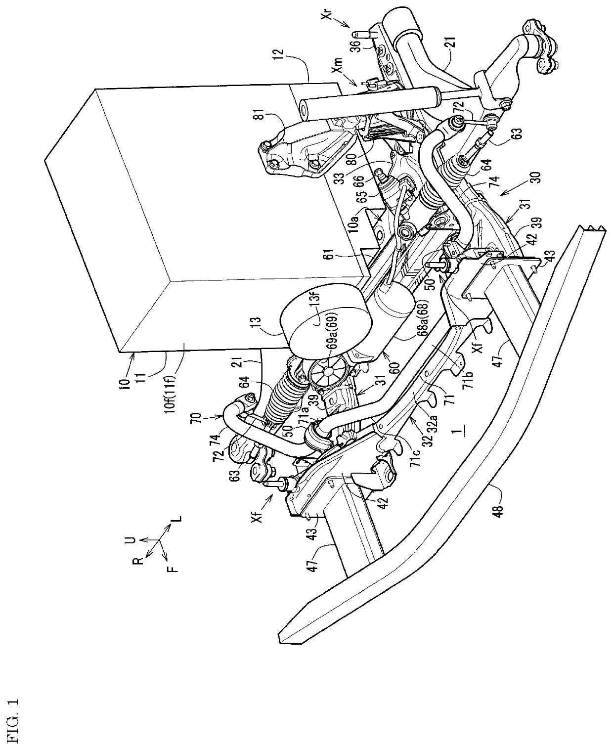
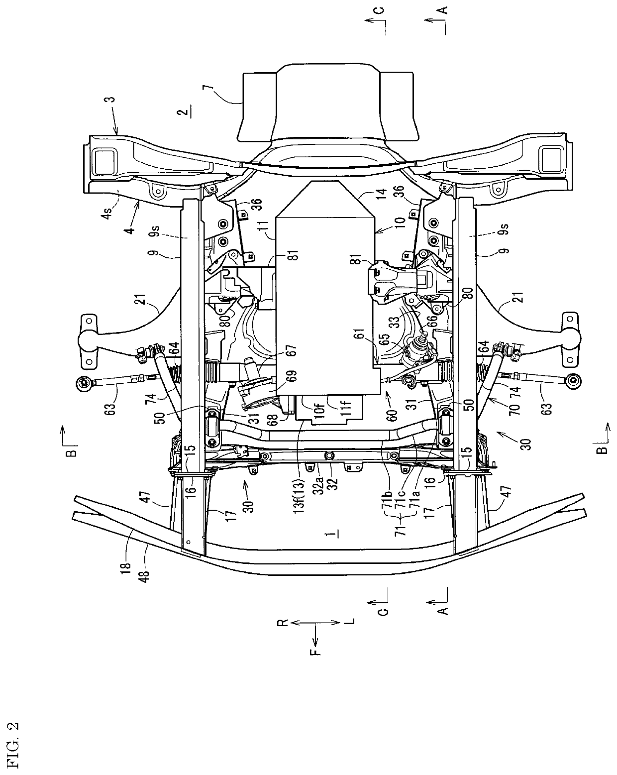
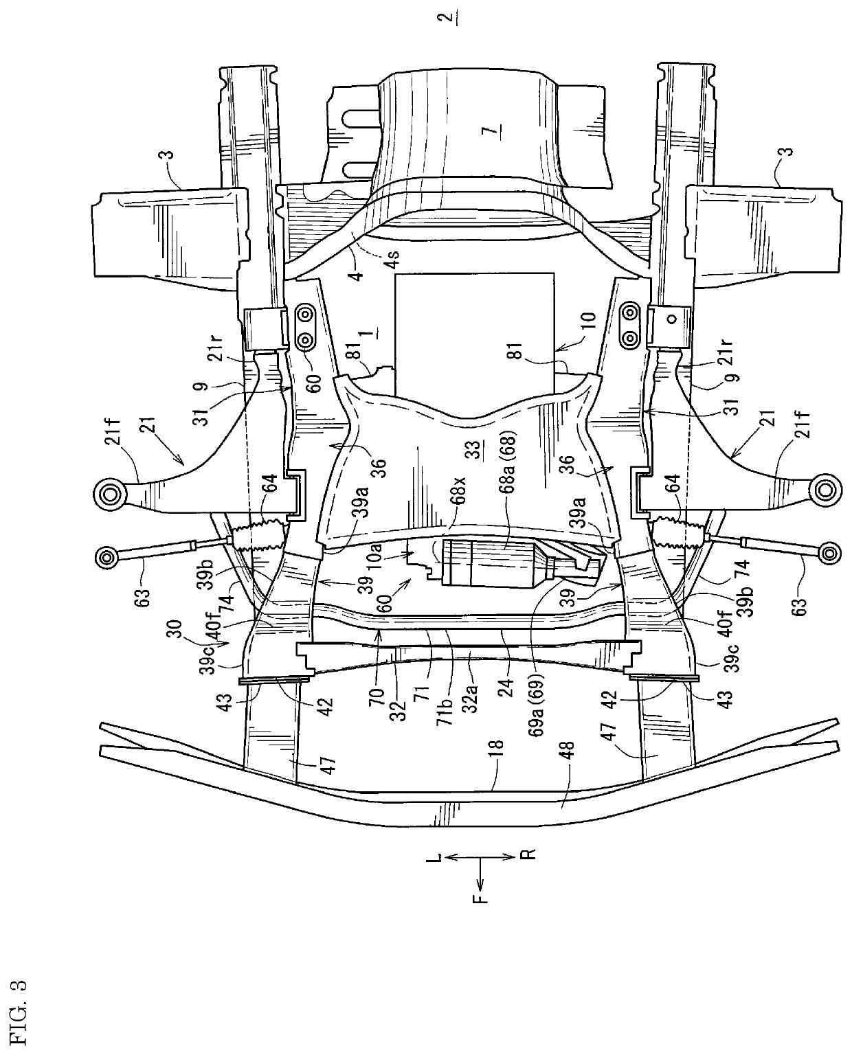
[0046]Referring to FIGS. 1 to 10, a description will be given of a front vehicle body structure having a suspension subframe structure of the present embodiment.

[0047]In the figures, an arrow F represents a vehicle frontward direction, an arrow U represents a vehicle upward direction, an arrow R represents a vehicle rightward direction, and an arrow L represents a vehicle leftward direction.

[0048]As shown in FIGS. 1 and 4, the front vehicle body structure includes: an engine 10 disposed in an engine compartment 1 partitioned from a vehicle interior 2 by a dash panel 3 (dash lower panel) (see FIGS. 1 to 3); front side frames 9 (see the same figures) extending in a vehicle front-rear direction at respective sides of the engine compartment 1; a suspension subframe structure 30 (hereinafter referred to as a “subframe 30”) supported by the front side frames 9.

[0049]In this embodiment, the drive system of the vehicle is a front engine rear drive (FR) system. As shown in FIG. 1, the engine...


PUM


Abstract

A subframe structure includes a pair of left and right front-rear frames each mounted with a lower arm; and a transverse member connecting front portions of the front-rear frames. The front-rear frames each includes a rear horizontal portion formed substantially horizontally, an inclined portion extending frontward and upward from a front end of the rear horizontal portion, and a front horizontal portion extending horizontally frontward from a front end of the inclined portion. The transverse member is jointed at left and right ends thereof to the front horizontal portions respectively corresponding to the left and right ends, a rear end of the front horizontal portion is disposed to be positioned frontward of a front end of an engine, and the front-rear frames are deformed into a Z shape in vehicle side view in an event of a front-end collision and thereby energy of the front-end collision is absorbed.

Description

BACKGROUNDTechnical Field[0001]The present disclosure relates to a subframe structure for a front suspension including a pair of left and right front-rear frames mounted with respective suspension arms of the front suspension, and a transverse member connecting front portions of the left and right front-rear frames.Background Art[0002]Typically, a subframe structure is supported by a pair of left and right front side frames extending frontward from a dash panel installed at a front side of a vehicle interior. The front side frames are provided at their respective front ends with a pair of left and right main crash cans, and a bumper beam is provided at front ends of the main crash cans so as to extend in a vehicle width direction.[0003]The subframe structure is provided at its front end with a pair of left and right sub crash cans, and a sub bumper beam is provided at front ends of the sub crash cans so as to extend in a vehicle width direction.[0004]As exemplified in Japanese Paten...

Claims


Application Information

Patent Timeline
Patent Type & Authority Patents(United States)
IPC IPC(8): B62D21/02B60G7/00B60K5/04B62D21/11B62D21/15
CPCB62D21/02B60G7/008B60K5/04B62D21/11B62D21/155B62D21/152B62D25/082B62D25/08
Inventor OKAMOTO, HIROYUKIKUROHARA, FUMIHIROKURODA, IPPEIHONJI, HIROMASASAWADA, YOSUKE
Owner MAZDA MOTOR CORP
Why Eureka
Try Eureka