
Process and a system for hydrocarbon steam cracking

a hydrocarbon and steam cracking technology, applied in the direction of hydrocarbon oil treatment products, thermal non-catalytic cracking, gas-gas reaction processes, etc., can solve the problems of unfavorable hydrocarbon thermal cracking and energy-intensive steam cracking process, and achieve the effect of simple, more economical process, and simple process

Active Publication Date: 2021-06-29
SABIC GLOBAL TECH BV
View PDF24 Cites 0 Cited by
  • Summary
  • Abstract
  • Description
  • Claims
  • Application Information

AI Technical Summary

Benefits of technology

The present invention relates to a process for increasing the efficiency of production of high-pressure steam by vaporizing hydrocarbon feedstock using low-temperature heat transfer medium and directly feeding the vaporized feedstock to a steam cracking furnace. This eliminates the need for the furnace to vaporize the feedstock, making more energy available for the production of superheated very high-pressure steam. The process also allows for the separation of lighter components from the feedstock using low-cost heat sources, thereby increasing the efficiency of the whole process. Overall, this invention offers a more economical and efficient way to produce high-pressure steam.

Problems solved by technology

Steam cracking is an energy intensive petrochemical process.
It is also not just possible to raise the pressure of these fractionating processes, since this will influence the separation or / and requires a higher temperature at the bottom, which will result in undesired thermal cracking of the hydrocarbons in the fractionating process.

Method used


Image

  • Process and a system for hydrocarbon steam cracking
  • Process and a system for hydrocarbon steam cracking
  • Process and a system for hydrocarbon steam cracking

Examples


Embodiment Construction

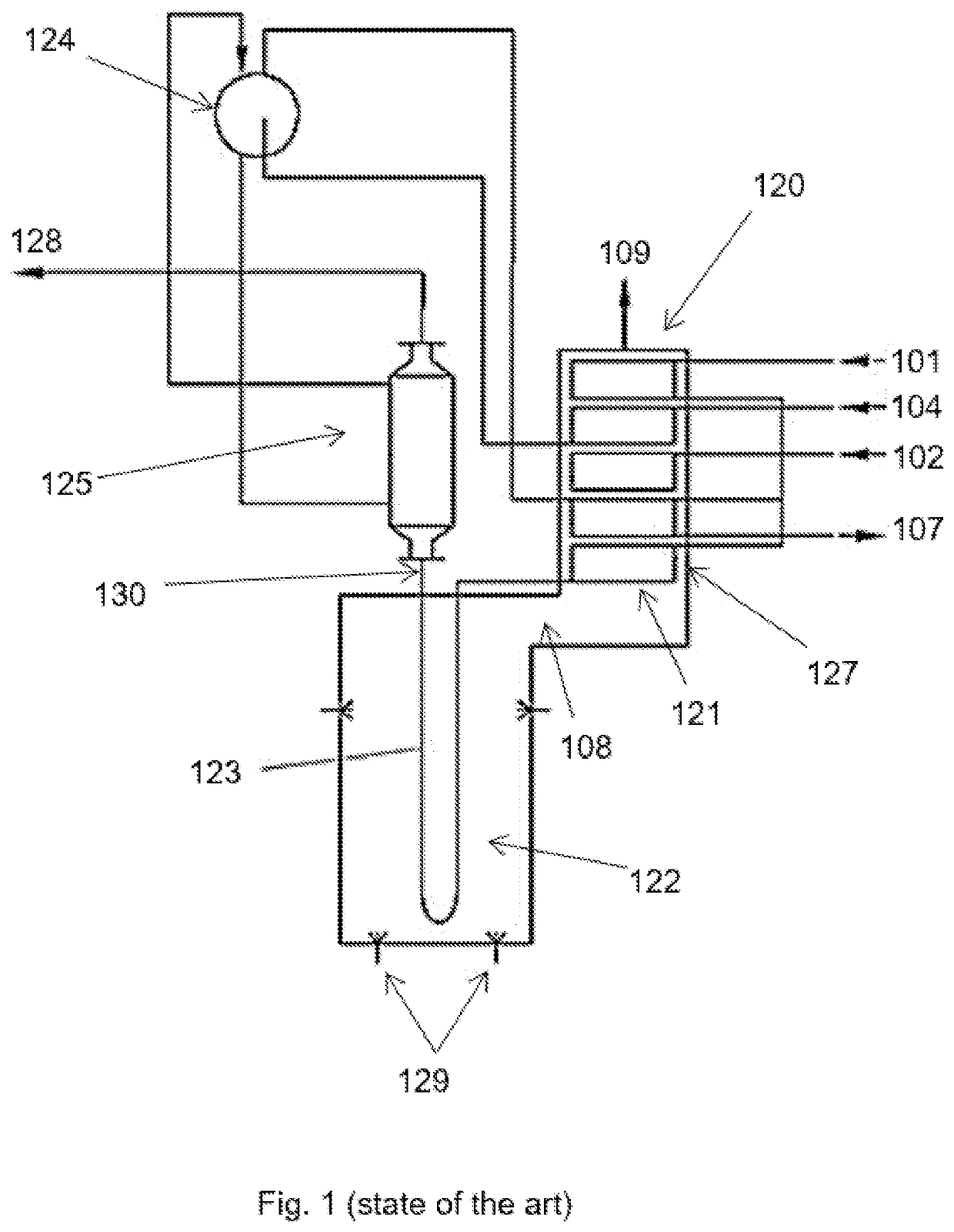
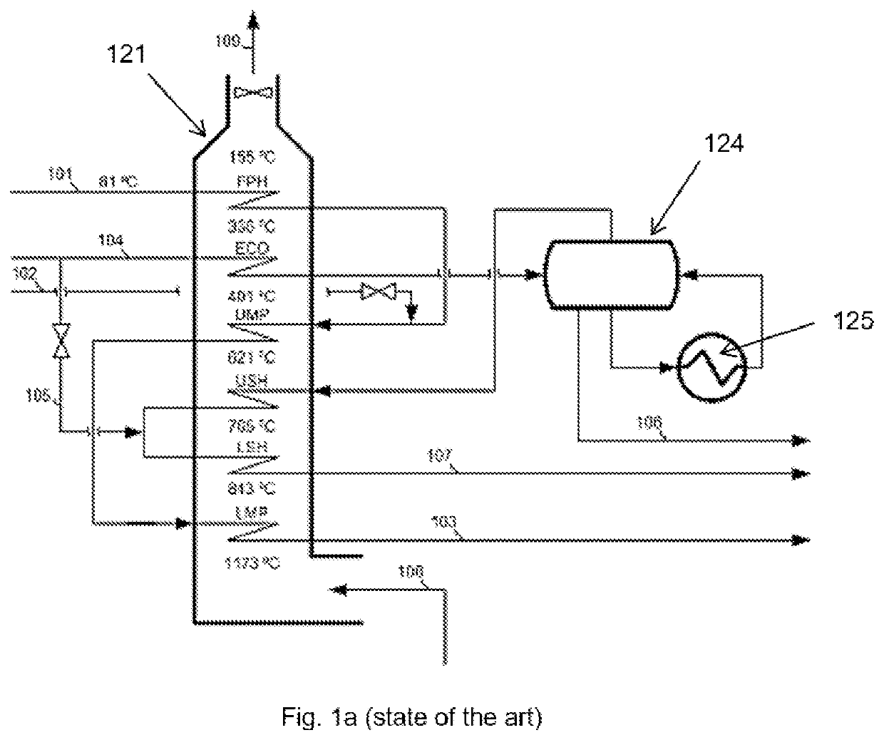
[0052]FIG. 1 shows a principal arrangement according to the state of the art of a steam cracking furnace system (derived from Ullman, Encyclopedia of industrial chemistry, p. 470 2012 Wiley-VCH Verlag GmbH & Co. KGaA, Weinheim). The system comprises a steam cracking furnace 120, having a radiant section 122, and a convection section 121. The radiant section has burners 129 for heating a fired tubular reactor 123 wherein the actual steam cracking of the hydrocarbon feedstock occurs. The flue gas from the burners 129 flows past the fired tubular reactor 123 to provide the necessary energy for the endothermic steam cracking process within the tubular reactor 123. The flue gas subsequently 108 flows to the convection section 121 of the steam cracking furnace 120.

[0053]Hydrocarbon feedstock can be introduced in an inlet stream 101, which is led to convection banks in 127 for superheating in the convection section 121 of the steam cracking furnace. The convection banks 127 will be detaile...


PUM

PropertyMeasurementUnit
temperatureaaaaaaaaaa
pressureaaaaaaaaaa
temperatureaaaaaaaaaa

Abstract

A process for steam cracking hydrocarbon feedstock in a steam cracking furnace, the process comprising superheating hydrocarbon feedstock using flue gas from a radiant section of the steam cracking furnace in hydrocarbon feedstock superheating means or the hydrocarbon feedstock superheater, superheating steam from the steam generator using the flue gas from the radiant section of the steam cracking furnace in second heat exchanging means or a second heat exchanger, steam cracking the super-heated hydrocarbon feedstock from the hydrocarbon feedstock superheating means or the hydrocarbon feedstock superheater into cracked gas in a fired tubular reactor, vaporizing the hydrocarbon feedstock, using hydrocarbon feedstock vaporizing means, wherein the hydrocarbon feedstock vaporizing means or the hydrocarbon feedstock vaporizer are heated with a heat transfer medium having a temperature less than or equal to 350° C. and feeding the vaporized hydrocarbon feedstock to the steam cracking furnace.

Description

CROSS-REFERENCE TO RELATED APPLICATION[0001]This application is a national phase under 35 U.S.C. § 371 of International Application No. PCT / IB2017 / 056124, filed Oct. 4, 2017, which claims the benefit of priority of European Patent Application No. 16192716.5 filed Oct. 7, 2016, the entire contents of each of which are hereby incorporated by reference in their entirety.FIELD OF THE INVENTION[0002]The invention relates to a process and a system for hydrocarbon steam cracking.BACKGROUND[0003]Steam cracking is a petrochemical process wherein saturated hydrocarbons having long molecular structures are broken down into smaller saturated or unsaturated molecules.[0004]Steam cracking, also referred to as pyrolysis, has long been used to crack various hydrocarbon feedstocks into olefins, preferably light olefins such as ethylene, propylene, and butylenes. Conventional steam cracking utilizes a pyrolysis furnace which has two main sections: a convection section and a radiant section. The hydro...

Claims


Application Information

Patent Timeline
Patent Type & Authority Patents(United States)
IPC IPC(8): C10G9/36C10G7/00B01D3/38B01J12/00B01J19/00B01J19/24C10G55/04
CPCC10G9/36B01D3/38B01J12/005B01J19/0013B01J19/2415C10G7/00C10G55/04B01J2219/00103B01J2219/00157C10G2300/807C10G2400/20
Inventor VAN WILLIGENBURG, JORIS
Owner SABIC GLOBAL TECH BV
Learn More