Method of steam generation by spraying water onto a duct within a chamber having divider walls

a technology of dividing wall and duct, which is applied in the direction of indirect heat exchangers, machines/engines, light and heating apparatus, etc., can solve the problems of difficult heat exchanger provision, and achieve the effect of plentiful and inexpensive sources of energy

Active Publication Date: 2018-04-17
TINMAN +1
View PDF27 Cites 2 Cited by
  • Summary
  • Abstract
  • Description
  • Claims
  • Application Information

AI Technical Summary

Benefits of technology

[0010]Preferably the temperature in the cell is greater than 250 degrees F. so as to generate superheated vapor instantly. In addition the temperature is maintained well above 212 degrees F. in order to avoid the heat loss which occurs in the in lines to turbine causing undesirable condensation.
[0055]The shape of the cell can vary widely since the shape has little effect on the operation within the cell which is controlled by the back pressure on the cell and the injection of the liquid in small streams or squirts of additional liquid into the pressurized super-heated vapor within the cell. The surfaces can be parallel so that the distance is constant and the liquid is sprayed from one surface toward the other, but again this is not essential. This allows the heat to reach from the surfaces to the interior of the cell to provide the flash evaporation. The distance between the surfaces can also vary widely and for example they could be shaped so that they are grooved or scalloped thereby optimizing contact area with a heat source. In other words, there are ways to increase surface area within the cell, thereby increasing steam production and controlling / influencing the rate of heat transfer.
[0059]In some cases such as for an exhaust manifold, the cell is formed by casting so that one wall is formed by the manifold itself while the other wall defining the second surface is formed as a spaced covering layer. In this way a cast manifold, incorporating a cell, can be shaped to precisely and uniformly match the existing manifold to avoid interfering with its design or function and the resulting cast manifold includes the outer layer which defines the cell as an additional layer or shell. In some cases the gas flows in the manifold are unchanged by fins or other obstructions which could interfere with the proper operation of the engine or other construction / source which produces the heat. Thus, in one example the first surface is cylindrical. However in some cases, fins, bars and other designs of obstruction can be used to aid transfer of heat to the inner wall surrounding the duct. In this case the shape and design of the manifold may need to be changed to accommodate the obstructions, which can interfere with exhaust flow, to avoid an unacceptable increase in back pressure at the exhaust ports.
[0066]In one advantageous arrangement, the vapor from the turbine is condensed in a return pipe extending into the supply tank so that the liquid in the supply tank acts to cool the vapor in the pipe while heating the liquid in the tank. The return pipe may include a diffuser for injecting the condensed liquid and or vapor into the liquid in the tank. Generally a radiator or other heat extraction system will be required to remove some of the excess heat to prevent the liquid from boiling in locations where it is intended to be liquid. Typically the radiator is located upstream of the condenser.

Problems solved by technology

However there remains difficulty in providing a heat exchanger which extracts heat at a suitable efficiency to make this system operate effectively.

Method used


Image

  • Method of steam generation by spraying water onto a duct within a chamber having divider walls
  • Method of steam generation by spraying water onto a duct within a chamber having divider walls
  • Method of steam generation by spraying water onto a duct within a chamber having divider walls

Examples


Embodiment Construction

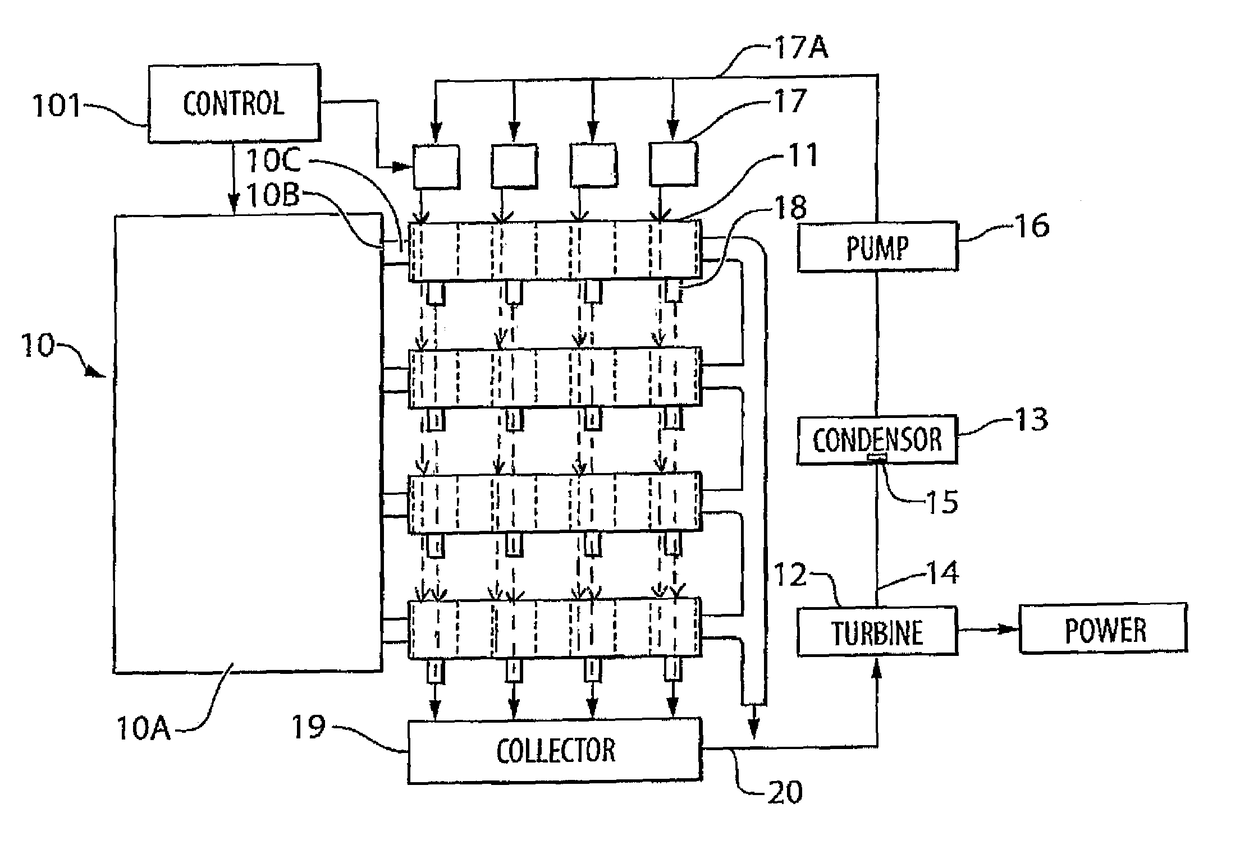
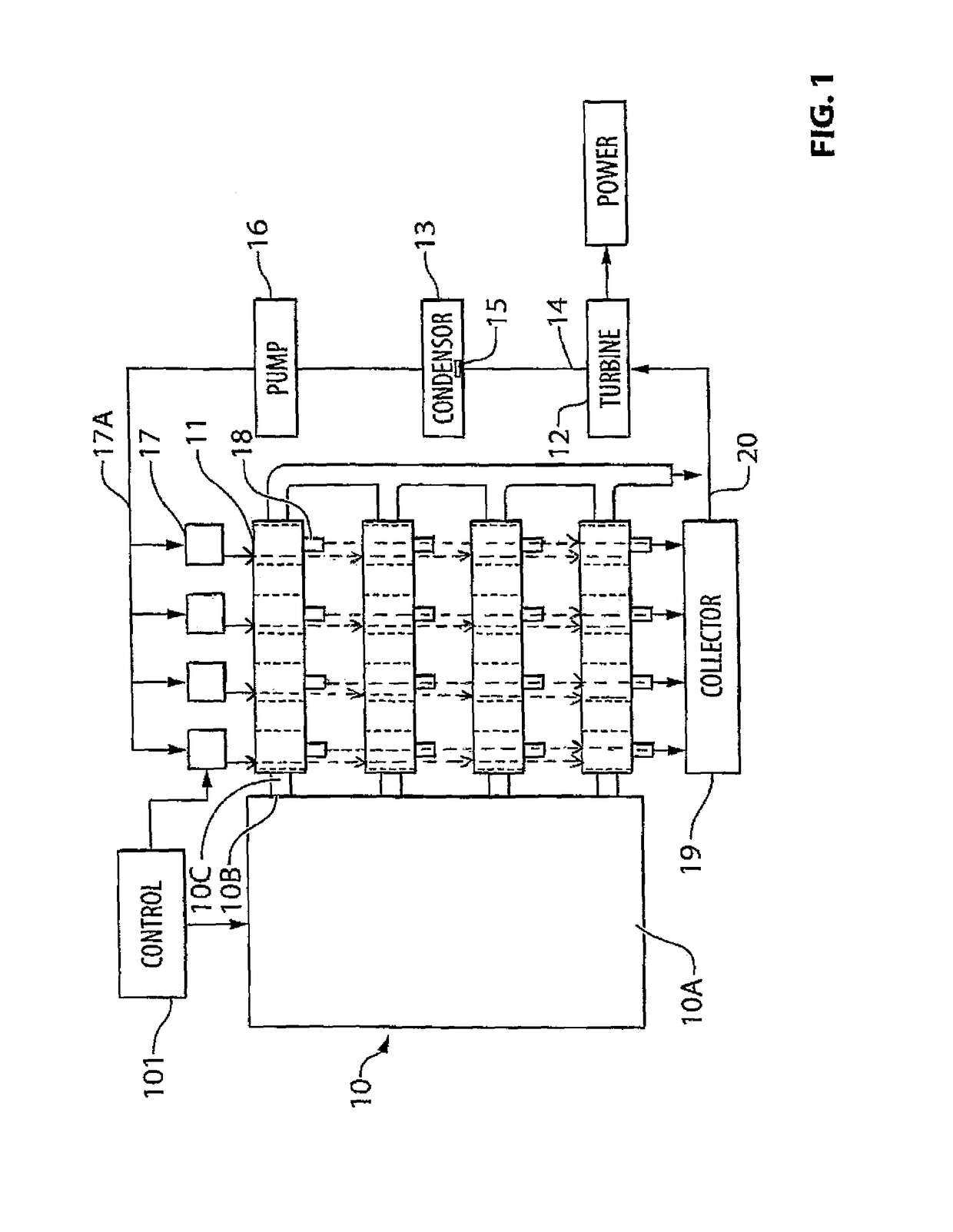
[0079]As shown in the Figures there is provided an apparatus and method for evaporating a liquid to generate a pressurized vapor. This comprises a heat source 10 in the form of an engine 10A with exhaust ports 10B feeding exhaust ducts 10C.

[0080]At each duct 10C is provided a series of vaporization cells or cores 11 developing steam for a turbine 12 driven by the vapor generated by the cell 11, a return tank 13 for the condensing vapor, a return pipe 14 to carry the steam from the outlet of the turbine which includes a diffuser 15 and a pump 16 to transfer the liquid back to the cell through injectors 17 through lines 17A.

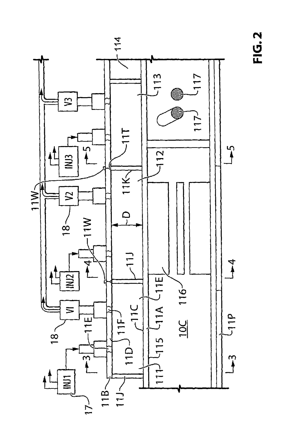
[0081]Each cell 11 includes walls defining two spaced surfaces 11C, 11D with an open chamber 11E therebetween with the surfaces located on the inside of walls 11A and 11B.

[0082]The walls 11A is in communication with a source of heat from the exhaust 10B within the duct 10C sufficient to maintain the surfaces at a temperature such that the liquid injected by injecto...


PUM

PropertyMeasurementUnit
pressureaaaaaaaaaa
pressureaaaaaaaaaa
operating pressureaaaaaaaaaa

Abstract

Liquid is flash evaporated in a series of cells along and surrounding an exhaust duct to generate a pressurized vapor where at least one of the surfaces is in communication with the source of heat sufficient to maintain the surface at a temperature such that the liquid injected into the chamber is substantially instantly converted to a superheated vapor with no liquid pooling within the chamber. The liquid is introduced by controlled injectors operating at a required rate. Each of the cells is periodically discharged by a pressure controlled relief valve and the vapor from the cells combined to form a continuous stream feeding a turbine or other energy conversion device. The outer wall of the cell is offset so that it contacts the inner wall at one point around the periphery. Heat transfer ribs and bars can be provided in the duct to provide increased heat transfer where necessary.

Description

[0001]This application claims the benefit under 35 USC 119 (e) of Provisional Application 61 / 546,952 filed Oct. 13, 2011, the disclosure of which is incorporated herein by reference.[0002]This invention relates to an apparatus for vaporization which can be used for example in a Rankine cycle engine to generate power from waste heat using a turbine. Such waste heat is often available from the exhaust gases of various combustion systems, such as internal combustion engines or furnaces, but other sources of heat can be used. In addition other uses of the vaporized gas, typically steam, are possibleBACKGROUND OF THE INVENTION[0003]However there remains difficulty in providing a heat exchanger which extracts heat at a suitable efficiency to make this system operate effectively. Typical heat exchanger use tubes often with fins to transfer heat from the heating medium into liquid carried within the tube so that the liquid in the tube evaporates and discharges as steam at the remote end of ...

Claims


Application Information

Patent Timeline
Patent Type & Authority Patents(United States)
IPC IPC(8): F22B27/16F28D21/00F22G7/14F28F1/40B01B1/06F01K23/10F28D7/10F22B37/60F01K23/06F01N5/02
CPCF22G7/14B01B1/06F01K23/065F01K23/10F22B37/60F28D7/10F28D21/001F28F1/40F22B27/16F01N5/02
Inventor WEIGOLD, THEODORE S.TOUCHETTE, SHANE M.
Owner TINMAN
Why Eureka
Try Eureka