Process for producing a highly transparent impact-resistant glass ceramic

a technology of impact-resistant glass and ceramics, which is applied in the direction of chemistry apparatus and processes, weapons, protective equipment, etc., can solve the problems of interference fringe patterns, time-consuming and cost-intensive linkage of individual layers and plastic materials to each other, and the inherent color of transparent glass ceramics is too strong, etc., to achieve high bullet penetration resistance, high transparency, and high resistance to bullet penetration

Active Publication Date: 2015-05-14
SCHOTT AG
View PDF1 Cites 0 Cited by
  • Summary
  • Abstract
  • Description
  • Claims
  • Application Information

AI Technical Summary

Benefits of technology

[0007]Another object of the present invention is to provide glass ceramic plates exhibiting high overall transmission for visible light. In particular, these glass ceramic plates show a high overall transmission for visible light which manifests itself in a high brightness value for transmitted standard light A under 2° observation) (YA / 2°).
[0069]The armored glass according to the invention ensures maximum energy absorption when a bullet strikes. This splinter-proof design preferably serves to protect the persons present in a motor vehicle or building provided with such an armored glass from being hit by flying glass splinters stemming from a glass pane hit by a bullet.

Problems solved by technology

Until now, the inherent color of transparent glass ceramics has been too strong.
The temperature- and pressure-controlled process of linking the individual layers and plastic materials to each other, in particular, is time-consuming and cost-intensive.
The many interfacial transitions between glass plates and plastic materials result in poor transmission characteristics which may lead to the formation of interference fringe patterns in the form of Newton fringes.
Also, the large amount of glass, namely the high number of glass plates in the known bullet-proof plates results in their exhibiting a very high weight per unit area.
The high weight per unit area leads to a significant construction cost for installation and vitrification.

Method used


Image

  • Process for producing a highly transparent impact-resistant glass ceramic
  • Process for producing a highly transparent impact-resistant glass ceramic

Examples


examples

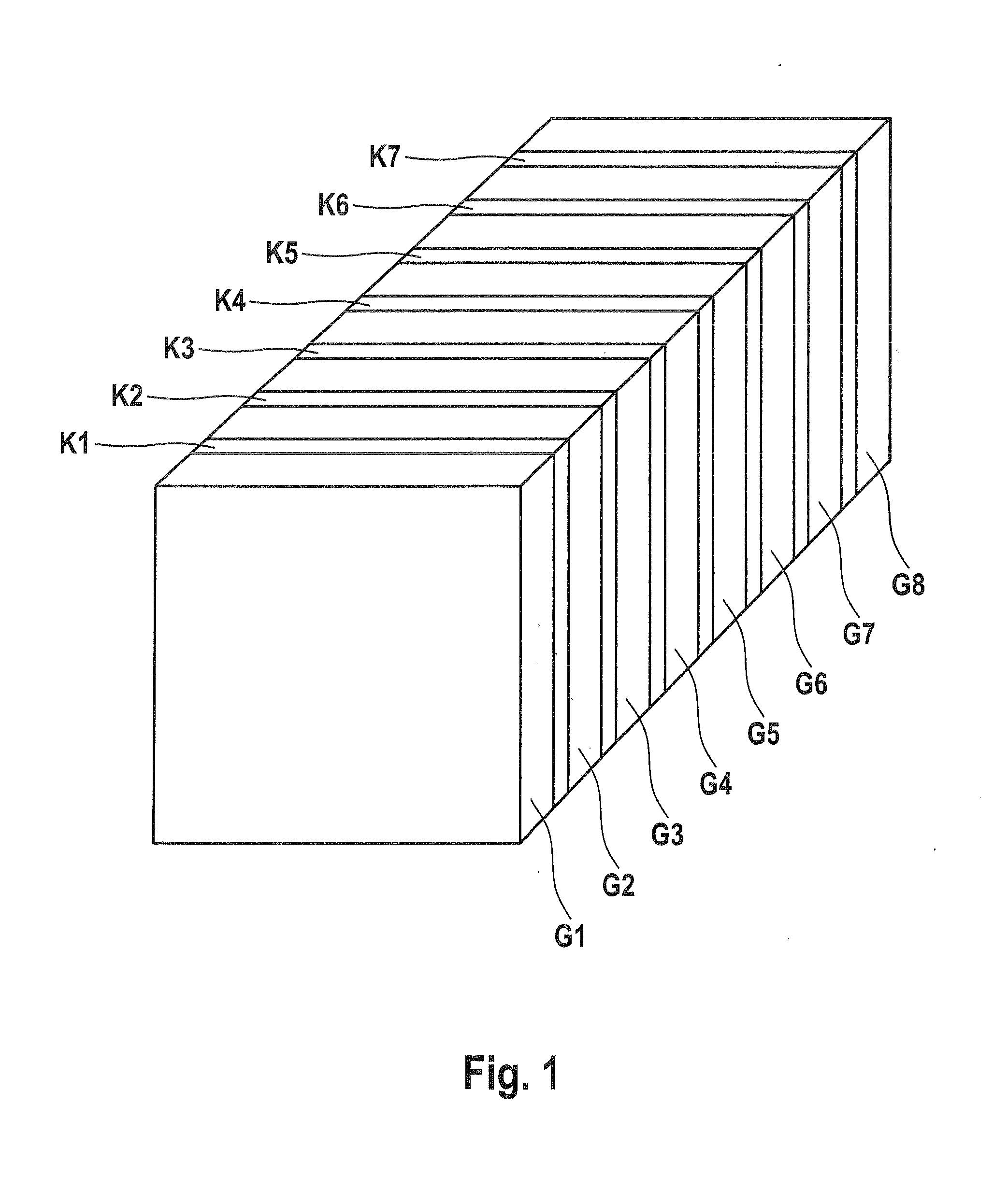
[0073]Four different glass ceramics of different composition, examples 1 to 4 in Table 1 here below, were prepared (data are given in wt. % based on oxides). The brightness value YA,2° Is GIVEN for a glass thickness of 4 mm and the linear thermal expansion coefficient (CTE) is given for the range between 30 and 700° C. The linear thermal expansion coefficient CTE was determined in the 30 to 700° C. temperature range in accordance with DIN ISO 7991 by use of a Thermal Dilatometric Analyzer, Harrop Model TD 710.

[0074]To prepare the glass ceramics, first a green glass of the same composition was prepared in the usual manner. From this green glass, glass plates of the desired thickness were then made. The glass plates were then ceramized in the known manner to form glass ceramic plates, the nucleating agents having been formed in the glass at a temperature of 750° C. and a residence time of 20 minutes. The glass was then heated to the crystallization temperature of 830° C. The crystalli...


PUM

PropertyMeasurementUnit
temperatureaaaaaaaaaa
thicknessaaaaaaaaaa
transparentaaaaaaaaaa

Abstract

The process for producing a transparent lithium aluminosilicate glass ceramic plate includes ceramicizing a green glass body of the Li2O—Al2O—SiO2 system using a ceramization program, which includes heating it, for the purpose of nucleation, to a temperature of 750° C.±20° C. and maintaining the temperature for 20±15 minutes, further heating the green glass body, for the purpose of ceramization, to a temperature of 900±20° C. and maintaining the to temperature for 20±15 minutes and then cooling to room temperature. The transparent plate has a thermal expansion coefficient (CTE) from −0.15×10⁻⁶ / K to +0.15×10⁻⁶ / K at 30 to 700° C. and a brightness value observed at an angle of 2° of ≧80 for a 4-mm thick plate for transmitted normal light.

Description

CROSS-REFERENCE[0001]This is a divisional of U.S. patent application Ser. No. 12 / 616,982, filed on Nov. 12, 2009, which claims priority of invention based on German Patent Application 10 2008 043 718.2 filed on Nov. 13, 2008 in Germany. The aforesaid German Patent Application contains subject matter described and claimed herein below.BACKGROUND OF THE INVENTION[0002]The inventions described herein comprise a transparent plate made of lithium aluminosilicate glass ceramic having a high transmission, a process for making same and also transparent plate laminates comprising at least one of the plates of the lithium aluminosilicate glass ceramic according to the invention and the use thereof as armored glass or in bullet-proof vests.[0003]Until now, the inherent color of transparent glass ceramics has been too strong. The reasons for the inherent color of transparent glass ceramics can vary. The constituents of the raw material mixtures for the melts contain the coloring element Fe as a...

Claims


Application Information

Patent Timeline
Patent Type & Authority Applications(United States)
IPC IPC(8): C03C10/00
CPCC03C10/0027B32B17/10045B32B17/10119B32B17/10761B32B2333/12C03C3/085F41H5/0407
Inventor ZACHAU, THILOSIEBERS, FRIEDRICHSCHIFFNER, ULRICHSCHAUPERT, KURT
Owner SCHOTT AG
Why Eureka
Try Eureka