Surgical screw system and related methods

a screw system and screw technology, applied in the field of surgical screw systems, can solve the problems of limiting this range of motion and threatening the critical elements

Inactive Publication Date: 2001-05-10
BLACKSTONE MEDICAL
View PDF0 Cites 431 Cited by
  • Summary
  • Abstract
  • Description
  • Claims
  • Application Information

AI Technical Summary

Problems solved by technology

4. Genetic or developmental irregularities, trauma, chronic stress, tumors and disease, however, can result in spinal pathologies whi

Method used


Image

  • Surgical screw system and related methods
  • Surgical screw system and related methods
  • Surgical screw system and related methods

Examples


Embodiment Construction

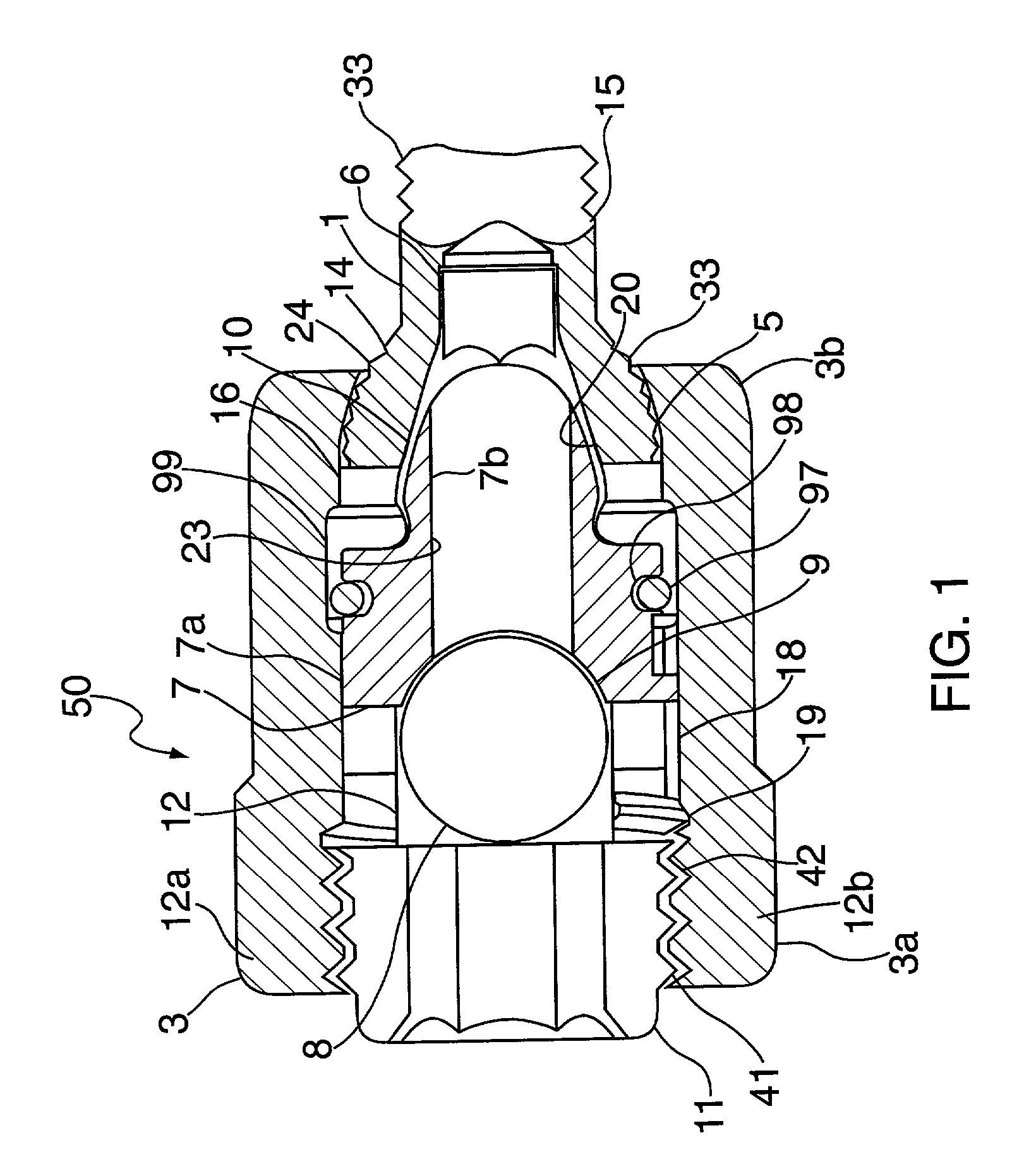
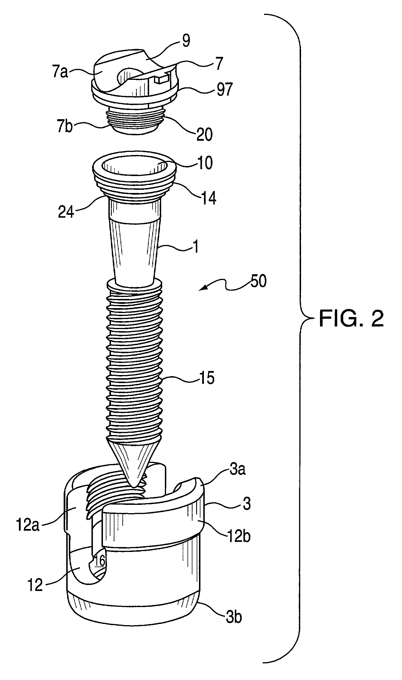
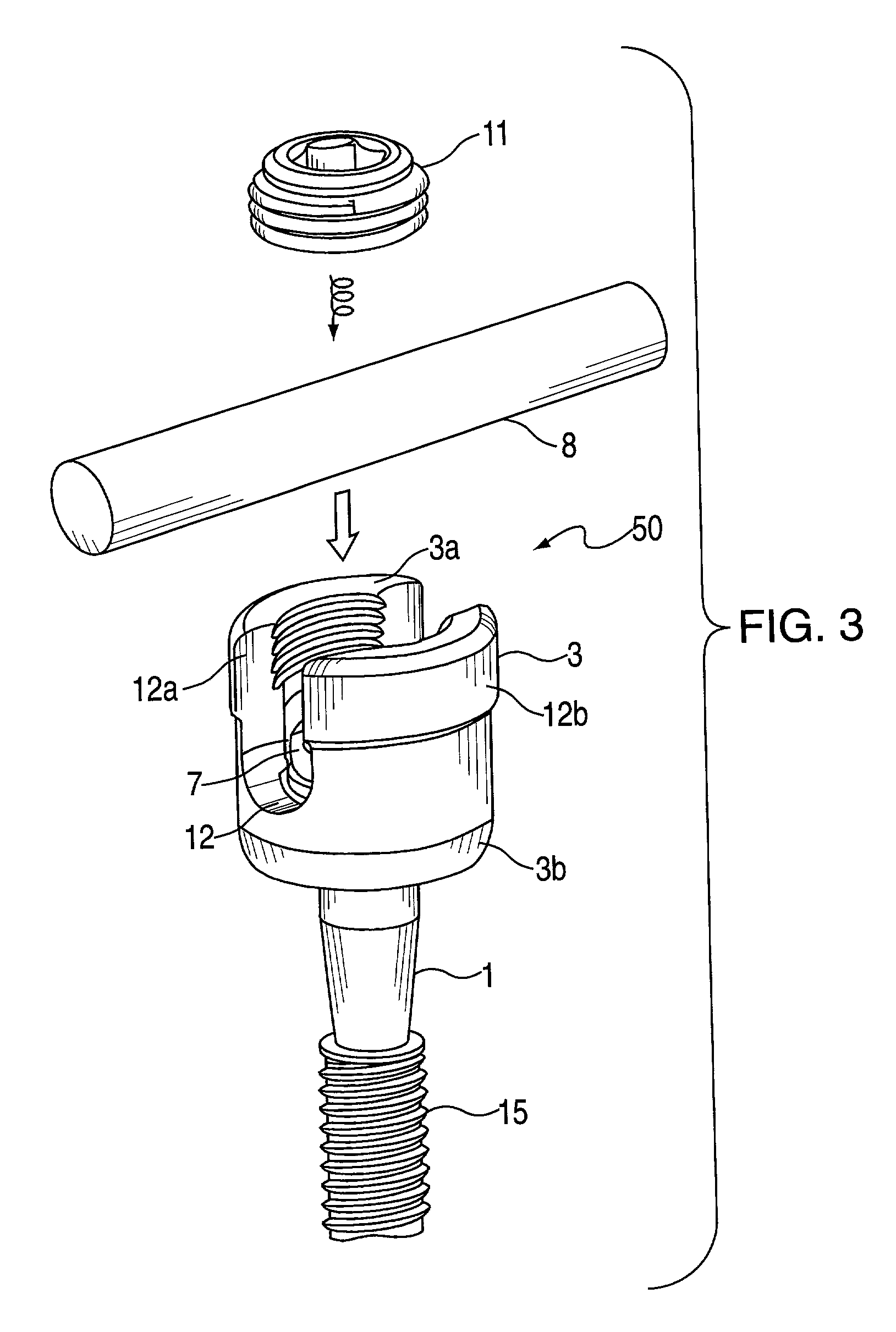
30. Referring now to the drawings wherein like reference numerals designate identical or corresponding parts throughout the several views, and more particularly to FIG. 1 wherein the surgical screw system 50 of the present invention is illustrated. The surgical screw system 50 comprises a screw member 1 having a head 14 and shaft 15. The head 14 has spherical undersurface 24 and a conical tapered recess 10. The system 50 further comprises a receiver member 3 having upper and lower portions, 3a and 3b respectively, a u-shaped rod receiving channel 12, and an axial bore 16. The u-shaped channel 12 has two lateral legs, 12a and 12b respectively, at the upper portion 3a of the receiver member 3 and forms an opening leading to the axial bore 16. The axial bore 16 near the lower portion 3b of the receiver member 3 includes an inwardly conical tapered surface 5. The conical surface 5 has a diameter larger than the shaft 15 of the screw member 1 and a diameter smaller than the head 14 of th...


PUM


Abstract

A surgical screw system for use with implantation rods includes a screw member, a receiver member, a pressure cap and a locking device. The screw member has a shaft and a head with a spherical undersurface and a conical tapered recess. The receiver member has an upper and lower portion, a u-shaped rod receiving channel and an axial bore. The u-shaped channel has two lateral legs at the upper portion and forms an opening leading to the axial bore. The axial bore near the lower portion includes an inwardly conical tapered surface which has a diameter larger than the shaft of the screw member but smaller than the head of the screw member. The conical surface forms a support upon which the spherical undersurface of the head of the screw member rests when the screw member is guided through the bore of the lower portion of the receiver member. The pressure cap is positioned within the axial bore and situated upon the head of the screw member. The locking device is designed for securing the rod within the u-shaped channel of the receiver member by applying a tightening torque upon the rod when positioned within the opening and the bore near the upper portion of the receiver member.

Description

BACKGROUND OF THE INVENTION:1. The present invention relates to a surgical screw system for use with implantation rods, and related methods of using a surgical screw system with implantation rods.2. The bones and connective tissue of an adult human spinal column consists of more than 20 discrete bones coupled sequentially to one another by a tri-joint complex. The complex consists of an anterior disc and two posterior facet joints. The anterior discs of adjacent bones are cushioned by cartilage spacers referred to as intervertebral discs. The over 20 bones of the spinal column are anatomically categorized as one of four classification: cervical, thoracic, lumbar, or sacral. The cervical portion of the spine which comprises the top of the spine up to the base of the skull, includes the first 7 vertebrae. The intermediate 12 bones are thoracic vertebrae, and connect to the lower spine comprising the 5 lumbar vertebrae. The base of the spine is a sacral bones (including the coccyx).3. ...

Claims


Application Information

Patent Timeline
IPC IPC(8): A61B17/70
CPCA61B17/7032A61B17/7037
Inventor LOMBARDO, ALAN
Owner BLACKSTONE MEDICAL
Why Eureka
Try Eureka