Spread spectrum receiver with multi-path correction

a spectrum receiver and multi-path technology, applied in the field of radio frequency receivers, can solve problems such as multi-path signals, multi-path effects, and additional signals, and achieve the effects of multi-path signals, multi-path effects, and typically unwanted signals

Inactive Publication Date: 2001-05-31
CSR TECH INC
View PDF99 Cites 48 Cited by
  • Summary
  • Abstract
  • Description
  • Claims
  • Application Information

AI Technical Summary

Problems solved by technology

GPS systems, as well as many other radio frequency (RF) communication systems utilizing frequencies high enough to be considered line of sight systems in which there must be a substantially direct line of sight between the transmitter(s) and receivers(s) for optimum operation, often suffer from multipath effects in which the receivers must process signals received over a multiplicity of different paths.
The multiplicity of signals being received results from additional, typically unwanted, signal paths including one or more reflections.
Multipath signals present a problem in systems, such as GPS systems, in which the time of arrival of the signal is to be measured or used because the time of arrival of the multipath signals depends on the length of the path(s) taken.
The straightforward processing of all signals, including multipath or reflected signals, often degrades the processing performed by the receiver.
This makes a highly directional antenna system almost completely unusable.
Multipath processing techniques currently used for complex receivers, such as GPS receivers, are often quite complex and subject to inaccuracies.
This technique of comparing processed and estimated correlation power, is complex and may be subject to error in that the partially processed signals relied on are themselves subject to degradation from many effects in addition to multipath effects including receiver limitations, which may reduce the accuracy or effectiveness of the multipath processing techniques.
If, as in most common cases, the multipath signal(s) are weaker than the direct path signals, the interference between such signals as received results in a predictable distortion of the correlation function.
When the correlation function of the composite is distorted to be wider than the correlation function expected for a direct path only signal, the distortion results in a lag error in which the prompt correlation lags the actual direct path signal received.
Similarly, when the correlation function of the composite is narrower than expected, the distortion results in a lead error in which the prompt correlation leads the time of arrival of the direct path signal.

Method used


Image

  • Spread spectrum receiver with multi-path correction
  • Spread spectrum receiver with multi-path correction
  • Spread spectrum receiver with multi-path correction

Examples


Embodiment Construction

)

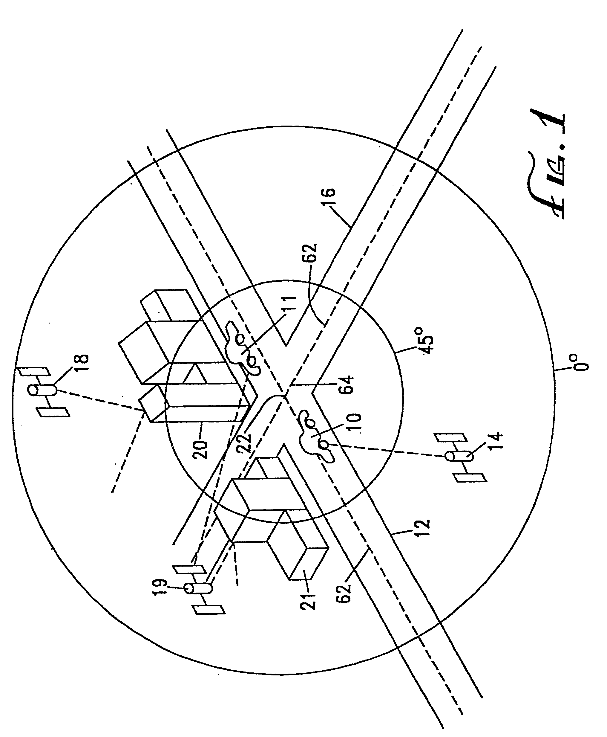
[0033] FIG. 1 is an overview illustration of the operation of a GPS car navigation system according to the present invention. The GPS car navigation system, described below in greater detail with respect to FIG. 2, is mounted in car 10 which is moving along the center of roadway 12. NAVSTAR satellite 14, in the lower left quadrant of the figure, is in view of car 10. A simulated GPS circular overhead display, positioned approximately over intersection 22 of roadway 12 and roadway 16 indicates that satellite 14 is between 0.degree. and 45.degree. degrees of elevation above the horizon as viewed from car 10.

[0034] For the purposes of illustration, satellite 18 is positioned 1 overhead between the elevation angles of 0.degree. and 45.degree.0 degrees. However, the line of sight between satellite 18 and car 10 is obscured by buildings 20 so that satellite 18 is not in view of car 10 at the position along roadway 12 as shown. Similarly, the line of sight between satellite 19 and car 10 ...


PUM


Abstract

A spread spectrum receiver uses a comparison of the magnitude of the code correlation amplitudes at equal power at a one chip spacing to the magnitude at a central position there between to determine if multipath interference is present. The lead or lag error from constructive or destructive multipath interference may also be determined. Inaccuracies due to such interference may then be corrected or minimized by, for example, determining the residual code phase error and / or the prompt or accurate code phase delay.

Description

CROSS REFERENCE TO RELATED APPLICATION(S)[0001] This application claims the priority of U.S. patent application filed Apr. 25, 1996, Ser. No. 08 / 637,457; U.S. patent application filed Apr. 25, 1996, Ser. No. 08 / 638,021; U.S. patent application filed Apr. 25, 1996, Ser. No. 08 / 637,537; U.S. patent application filed Apr. 25, 1996, Ser. No. 08 / 638,882; U.S. patent application filed Apr. 25, 1997, Ser. No. 08 / 846,067; U.S. patent application filed Jul. 25, 1997, Ser. No. 08 / 900,622; U.S. patent application filed Jul. 25, 1997, Ser. No. 08 / 900,418; U.S. patent application filed Jul. 25, 1997, Ser. No. 08 / 900,894; U.S. patent application filed Aug. 21, 1997, Ser. No. not yet assigned, U.S. Provisional Patent Application filed Sep. 16, 1996, Ser. No. 60 / 026,304; and U.S. Provisional Patent Application filed Mar. 28, 1997, Ser. No. 60 / 042,868.[0002] 1. Field of the Invention[0003] This invention relates in general to radio frequency receivers subject to the reception of multipath signals an...

Claims


Application Information

Patent Timeline
Patent Type & Authority Applications(United States)
IPC IPC(8): G01C21/26G01C22/00G01S1/00G01S5/14G01S19/48H04B1/707H04B1/7085H04B1/7115H04B7/216
CPCG01C21/26G01C22/00G01S19/11G01S19/22G01S19/29G01S19/30G01S19/37G01S19/47H04B1/707H04B1/7085H04B1/7115H04B7/216H04B2001/70706H04B2201/70715
Inventor CAHN, CHARLES R.CHANSARKAR, MANGESHKOHLI, SANJAI
Owner CSR TECH INC
Why Eureka
Try Eureka