
Demodulator having automatic quadrature control function

a demodulator and quadrature control technology, applied in the direction of pulse technique, phase-modulated carrier system, gain control, etc., can solve the problems of inability to say high precision of devices, device cannot be said to cope, device cannot be said to be of high precision, etc., to achieve the effect of ensuring operational stability

Inactive Publication Date: 2001-07-26
NEC CORP
View PDF7 Cites 18 Cited by
  • Summary
  • Abstract
  • Description
  • Claims
  • Application Information

AI Technical Summary

Benefits of technology

[0014] It is another object of the present invention, to provide a demodulator which renders it unnecessary to make precision adjustment on the modulator side and which assures operational stability and high reliability without producing deterioration in characteristics such as error rate for a prolonged time.

Problems solved by technology

That is, it is not possible with the conventional demodulator shown in FIG. 11 to correct quadrature deviation produced in modulation.
However, this device cannot be said to be of high precision.
In particular, the device cannot be said to cope with multi-value modulation system, such as QAM, such that, if this device is put to Practical use, the BER (bit error rate) tends to be lowered.
As described above, it is not possible in the conventional demodulators to correct the quadrature deviation produced at the time of modulation.
So, a quadrature adjustment process was required during device production etc., thus necessitating redundant time and operating steps.

Method used


Image

  • Demodulator having automatic quadrature control function
  • Demodulator having automatic quadrature control function
  • Demodulator having automatic quadrature control function

Examples


Embodiment Construction

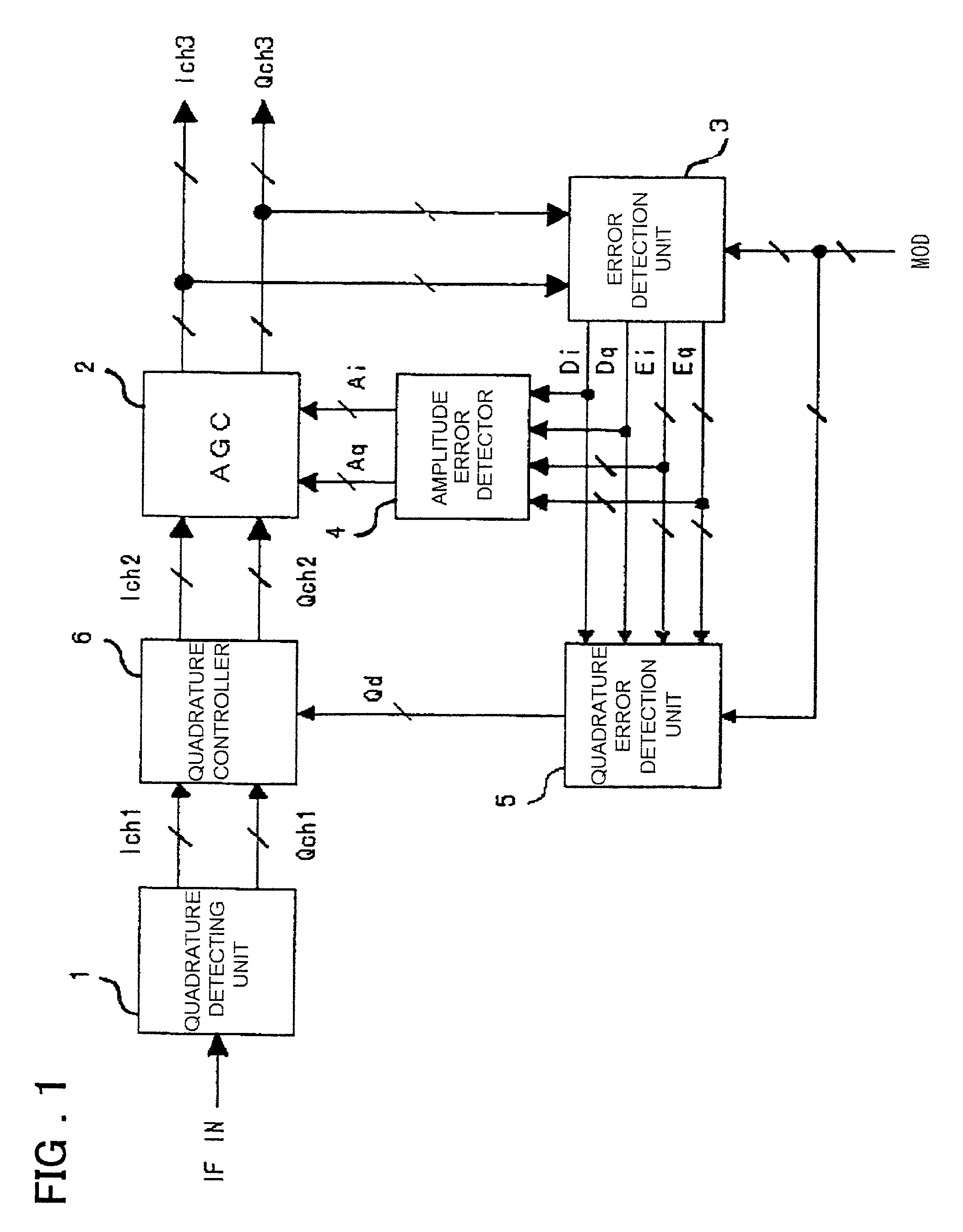
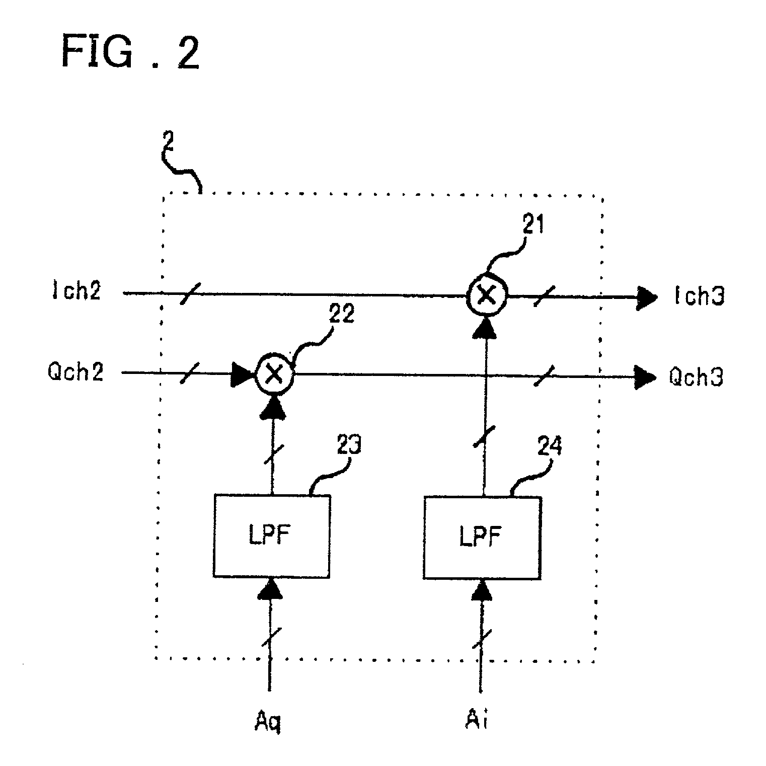
[0065] A preferred embodiment of the present invention is now explained. Referring to FIG. 1, a preferred embodiment of the demodulator of the present invention includes a quadrature detecting unit 1, a quadrature controller 6, and an automatic amplitude controller (AGC) 2 in this order of signal flow, and further a feed back circuitry comprising an error detection unit 3, an amplitude error detection unit 4 and quadrature error detection unit 5. The quadrature detecting unit 1 is fed as an input signal with an intermediate frequency (IF IN) signal for quadrature-detecting the input signal to output an in-phase component Ich1 and a quadrature component Qch1. The quadrature controller 6 is fed with an in-phase component and a quadrature component output from the quadrature detecting unit 1 to correct the quadrature error based on quadrature error signal Qd. The automatic gain controller AGC 2 is fed with the in-phase and quadrature components Ich2, Qch2 output from the quadrature con...


PUM


Abstract

A demodulator for automatically performing quadrature control in which there is no necessity for the modulator side to perform precision adjustment and deterioration in characteristics e.g., error rate is suppressed for long. The demodulator includes a quadrature controller fed with an in-phase component and a quadrature component output from the quadrature detecting unit to correct quadrature error between phases of in-phase and quadrature signals based on a quadrature error signal, an automatic gain controller AGC outputting in-phase and quadrature components of a demodulated signal corrected for amplitude errors by an amplitude error signal, an error detection unit fed with in-phase and quadrature components of the demodulated signal to output in-phase and quadrature components and polarity signals, an amplitude error detector outputting in-phase and quadrature components of the amplitude error to the AGC based on the in-phase and quadrature components and the respective polarity signals, and a quadrature error detection unit generating a quadrature error signal Qd based on the in-phase and quadrature components and the polarity signals to output the generated quadrature error signal to the quadrature controller.

Description

[0001] This invention relates to a demodulator and, more particularly, to a demodulator for automatically correcting errors in a detection signal of a quadrature detected modulated signal in a digital radio communication system.[0002] FIG. 11 shows a typical structure of a conventional demodulator. Referring to FIG. 11, this demodulator includes a quadrature detecting unit 1, an automatic amplitude controller (AGC) 3, an error detection unit 3 and an amplitude error detection unit 4.[0003] An input modulated signal is assumed to have been modulated in accordance with a quadrature modulation system, such as QPSK (quadrature phase shift keying) or QAM (quadrature amplitude modulation). The respective quadrature components (channels) are termed an in-phase component or channel (Ich) and a quadrature component or channel (Qch), respectively. A quadrature detecting unit 1 receives a quadrature modulated signal, as an IF (intermediate frequency) signal, and outputs an output signal as bas...

Claims


Application Information

Patent Timeline
IPC IPC(8): H04L27/00H04L27/22H04L27/38H03G3/30
CPCH04L27/0014H04L2027/0016H04L2027/0024
Inventor IEMURA, TAKAYA
Owner NEC CORP
Learn More