Eureka AIR delivers breakthrough ideas for toughest innovation challenges, trusted by R&D personnel around the world.

Milling tool and insert, particularly thread milling cutter

a technology of inserts and milling tools, which is applied in the direction of thread cutting tools, metal-working equipment, milling equipment, etc., can solve the problems of reducing the stability of tools, reducing the depth of grooves, threads, etc. produced on workpieces, and reducing the risk of loosening or breaking of fastening elements

Inactive Publication Date: 2001-08-30
VARGUS TOOL MFG
View PDF2 Cites 17 Cited by
  • Summary
  • Abstract
  • Description
  • Claims
  • Application Information

AI Technical Summary

Benefits of technology

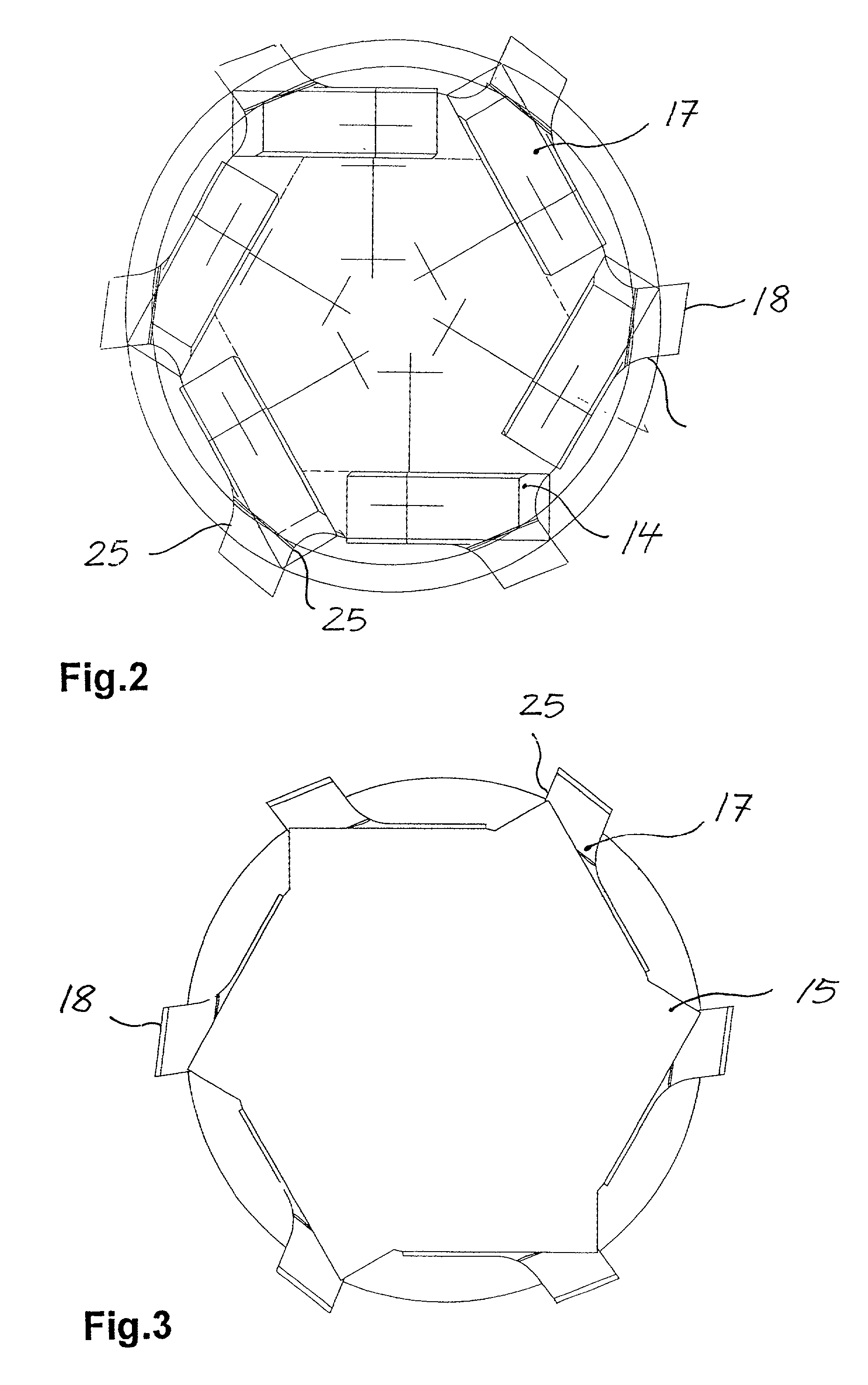
[0009] According to the invention the problem is solved by the features of claim 1. The bearing and orientation surfaces of the milling tool are consequently constructed for a substantially tangential reception of milling inserts, e.g. turning cutting bits or indexable inserts. A comparison with a conventional milling tool, where the milling inserts are positioned radially on the circumference of the cutter shank and are e.g. fixed by screws or wedges with the milling tool according to the invention shows that for the same diameter of the two shanks on the milling tool according to the invention it is possible to provide more milling inserts than with a conventional milling tool. Thus, the milling tool according to the invention can be equipped with a plurality of milling inserts. This is achieved by the tangential reception of the milling inserts. The milling capacity, i.e. the metal removal rate per time unit or revolution of such a milling tool is higher than conventional milling tools, so that the tool lifes also longer.
[0010] In the case of conventional milling tools the receptacles for the milling inserts are often constructed in such a way that on the circumference of the milling tool there are deep reception openings oriented radially to the milling cutter rotation axis, which reduces the tool stability. In the case of the milling tool according to the invention, this situation does notarise. Therefore the milling tool according to the invention, particularly when compared with a conventional tool with in each case the same number of fixed milling inserts, is more stable and compact than conventional milling tools.
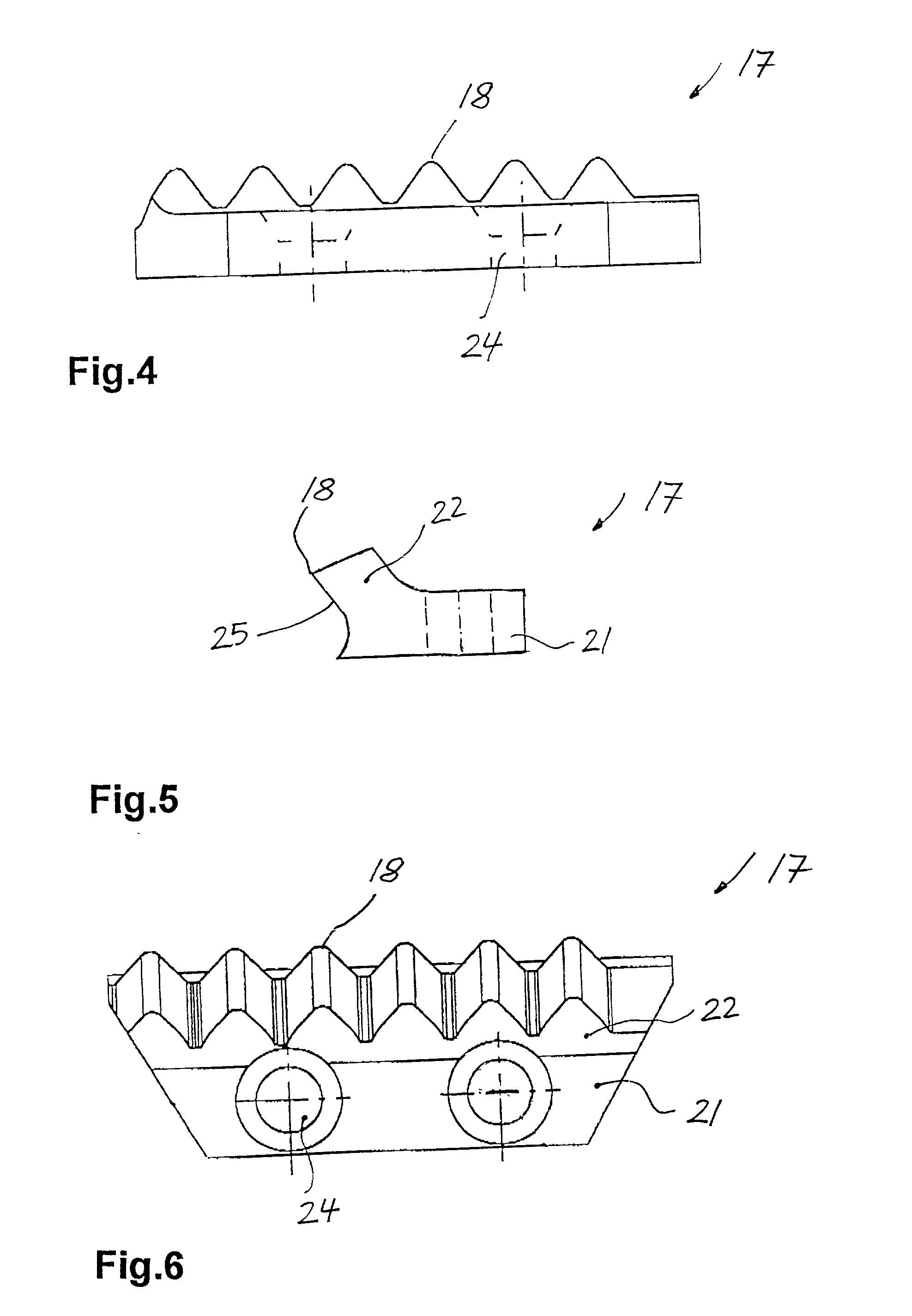
[0020] It is possible to construct the milling insert with chamfered edges directed towards a workpiece to be machined. This is in particular used with milling inserts having large dimensions in order to prevent any contact between said edges and the workpiece.

Problems solved by technology

In the case of conventional milling tools the receptacles for the milling inserts are often constructed in such a way that on the circumference of the milling tool there are deep reception openings oriented radially to the milling cutter rotation axis, which reduces the tool stability.
There is a high risk of loosening or breaks on the fastening elements, e.g. the shearing off of screws, etc.
Therefore the groove, thread, etc. produced on the workpiece no longer has a uniform depth.

Method used


Image

  • Milling tool and insert, particularly thread milling cutter
  • Milling tool and insert, particularly thread milling cutter
  • Milling tool and insert, particularly thread milling cutter

Examples


first embodiment

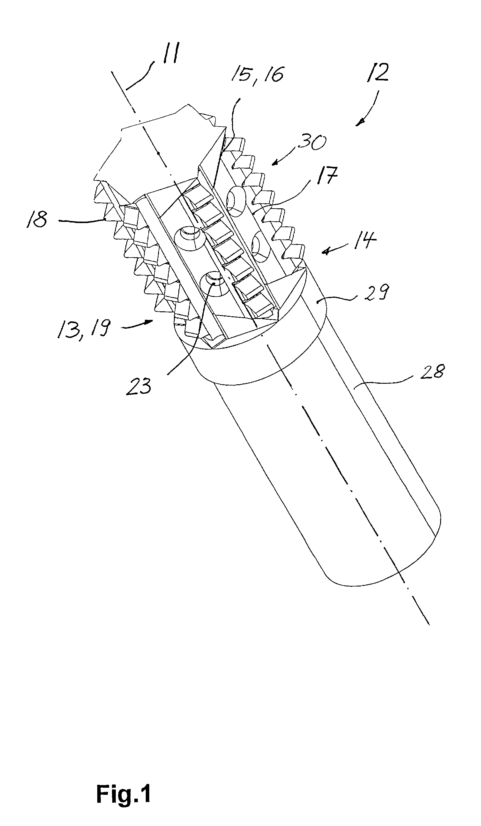
[0039] FIG. 1 shows a milling tool equipped with milling inserts 17. The milling tool has a solid body with a cylindrical cross-section. The milling tool is made from steel and the milling insert 17 from carbide. Such a milling tool embodiment e.g. has a diameter of 32 mm and a length of 129 mm. The milling tool has a holding area 28, a stop member 29 and a reception area 30. In operation the milling tool rotates about its centre axis, i.e. the rotational milling axis 11.

[0040] The holding area 28 has a cylindrical cross-section. It is chamfered at its end facing the reception area 30. In the first milling tool embodiment the reception area extends over somewhat more than half of the entire tool length. The stop member 29 is connected to the holding area 28. The stop member 29 has a larger diameter than the holding area 28 and its length is approximately 1 / 5 of the length of the holding area 28. The reception area 30 of the milling tool is connected to the stop member 29.

[0041] FIG....

fourth embodiment

[0048] FIG. 13 shows the milling tool in the form of a shankless hobbing cutter. The hobbing cutter has a through centre hole 32 for the introduction into a not shown mandrel-like mounting support. On the underside of the hobbing cutter is formed a through, radial groove 33, which protects the hobbing cutter against twisting on the mandrel--like mounting support.

[0049] FIG. 14 shows a fifth embodiment of the milling tool. As in the first embodiment according to FIG. 9, the milling tool has a holding area 28 and a reception area 30 with six receptacles 14. The receptacles 14 have in each case two bearing and orientation sections 34, 34a, whose inclined lateral faces form bearing and orientation surfaces 15.

[0050] The two bearing and orientation surfaces 15 of a receptacle 14 are inclined to a differing extent with respect to the horizontal. Thus, the bearing and orientation surface 15 is steeper on the lower bearing and orientation section 34 directed towards the holding area 28 than...


PUM


Abstract

The invention relates to a milling tool. The milling tool has bearing and orientation surfaces for a substantially tangential reception of milling inserts. The receptacles of the milling tool can be arranged in adjacent manner axially symmetrically to the rotational milling axis of the milling tool. The milling insert can be eccentrically braced in the milling tool receptacle.

Description

[0001] 1. Field of the Invention[0002] The invention relates to a milling tool, particularly a thread milling cutter according to the preamble of claim 1.[0003] 2. Description of the Prior Art[0004] Milling tools are generally known and are used in the most varied constructional forms for carrying out different milling tasks. Milling methods are subdivided on the basis of the surface produced, the tool shape and the kinematics, inter alia into plain, circular, profile and form milling, as well as hobbing. Profile milling e.g. includes the milling of threads or grooves.[0005] In thread milling the tool rotates about its own axis and simultaneously moves in three axes, namely the space axes x, y and z. The most important setting parameters are the milling cutter speed and the feed rate of the milling cutter in the xy-plane.[0006] In the case of milling tools it is known to place milling inserts radially with respect to the rotation axis. The milling inserts can be screwed or soldered ...

Claims


Application Information

Patent Timeline
Patent Type & Authority Applications(United States)
IPC IPC(8): B23G5/18
CPCB23G5/18B23G2200/10Y10T407/1725Y10T407/172
Inventor KICHIN, MICHAEL
Owner VARGUS TOOL MFG
Why Eureka
Eureka Blog
Learn More