
Transmitter apparatus and receiver apparatus and base station making use of orthogonal frequency division multiplexing and spectrum spreading

a technology of orthogonal frequency division and receiver apparatus, applied in the direction of frequency-division multiplex, orthogonal multiplex, pulse technique, etc., can solve the problems of increasing interference with adjacent cells, unable to continue communication, and how to arrange cells in the dynamic zone structur

Inactive Publication Date: 2001-09-13
KK TOSHIBA
View PDF2 Cites 70 Cited by
  • Summary
  • Abstract
  • Description
  • Claims
  • Application Information

AI Technical Summary

Benefits of technology

[0022] It is another object of the present invention to provide a transmitter apparatus, a receiver apparatus and a base station implemented with the transmitter and receiver apparatuses in which the interference between adjacent cells is effectively prevented even in the cell arrangement where the frequency resources as available are limited.
[0023] It is further object of the present invention to provide a transmitter apparatus, a receiver apparatus and a base station implemented with the transmitter and receiver apparatuses in which it is possible to obtain information necessary for taking appropriate control of the antenna in order to direct a beam to the mobile station that is located in a remote position where a communication link can be established only by securing a necessary antenna gain through the adaptive array antenna directed to that mobile station.
[0027] In a preferred embodiment, further improvement resides in that said transmission signal processing circuit is provided with an adaptive array antenna and wherein, when said receiver apparatus and said transmitter apparatus are located so remote from each other that the received signal level of said receiver apparatus is not sufficient to maintain the communication between said receiver apparatus and said transmitter apparatus with signals which are modulated on the basis of said orthogonal frequency division multiplexing modulation but not modulated on the basis of said spectrum spreading modulation, the direction of said receiver apparatus relative to said transmitter apparatus is detected by making use of a transmission signal which is modulated by said spectrum spreading modulation, followed by directing a beam of the adaptive array antenna to said mobile station to increase the received signal level of said receiver apparatus and make it possible to perform the communication between said receiver apparatus and said transmitter apparatus by orthogonal frequency division multiplexing.
[0031] In a preferred embodiment, further improvement resides in that said transmission signal processing circuit is provided with an adaptive array antenna and wherein, when said receiver apparatus and said transmitter apparatus are located so remote from each other that the received signal level of said receiver apparatus is not sufficient to maintain the communication between said receiver apparatus and said transmitter apparatus with signals which are modulated on the basis of said orthogonal frequency division multiplexing modulation but not modulated on the basis of said spectrum spreading modulation, the direction of said receiver apparatus relative to said transmitter apparatus is detected by making use of a transmission signal which is modulated by said spectrum spreading modulation, followed by directing a beam of the adaptive array antenna to said mobile station to increase the received signal level of said receiver apparatus and make it possible to perform the communication between said receiver apparatus and said transmitter apparatus by said first orthogonal frequency division multiplexing modulations.

Problems solved by technology

In recent years, it becomes an important issue to cope with interference due to delay spread through multipaths while the signal transmission rates of wireless communication systems have been increased.
For this reason, it is a technical issue how to expand the variable range of the coverage of a cell.
Furthermore, it is inevitable that the interference with an adjacent cell is increased while the coverage of a cell is expanded.
From this fact, there is a problem as to how to arrange cells in the dynamic zone structure.
Also, in the case of such a system in which the communication range is expanded by the antenna gain as obtained by directing the beam from an adaptive array antenna to the target mobile station, it is impossible to continue communication unless the antenna is directed to the mobile station.
In other words, while communication can be continued without controlling the direction of the antenna in the case where the mobile station is located within the service area, it is impossible to establish communication with a mobile station located outside of the service area unless the antenna is directed to the mobile station by beam control.
Accordingly, it is impossible to obtain information necessary for taking appropriate control of the antenna in order to direct a beam to the mobile station that is located in a remote position where a communication link can be established only by securing a necessary antenna gain through the adaptive array antenna directed to that mobile station.
For this reason, it is a technical issue to expand the variable range of the coverage of a cell.
Furthermore, it is inevitable that the interference with an adjacent cell is increased while the coverage of a cell is expanded.
From this fact, it is a technical issue how to arrange cells in the dynamic zone structure.
Furthermore, it is impossible to obtain information necessary for taking appropriate control of the antenna in order to direct a beam to the mobile station that is located in a remote position where a communication link can be established only by securing a necessary antenna gain through the adaptive array antenna directed to that mobile station.
In consequence, it is an important technical problem how to determine the initial position of a remote mobile station (the initial position determination).

Method used


Image

  • Transmitter apparatus and receiver apparatus and base station making use of orthogonal frequency division multiplexing and spectrum spreading
  • Transmitter apparatus and receiver apparatus and base station making use of orthogonal frequency division multiplexing and spectrum spreading
  • Transmitter apparatus and receiver apparatus and base station making use of orthogonal frequency division multiplexing and spectrum spreading

Examples


first embodiment

(FIRST EMBODIMENT)

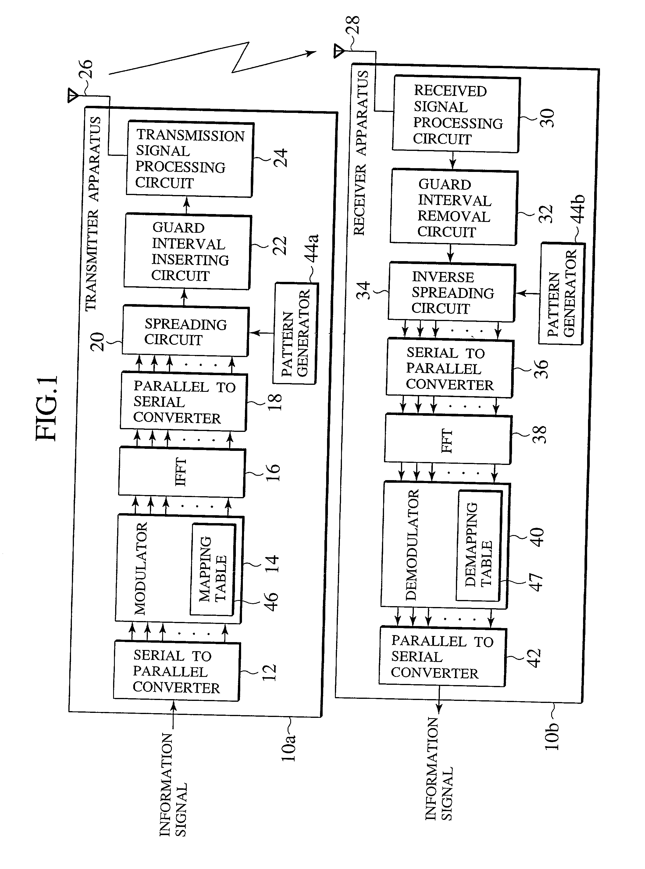
[0059] FIG. 1 is a block diagram showing a transmitter apparatus and a receiver apparatus in accordance with a first embodiment of the present invention. The transmitter apparatus and the receiver apparatus in accordance with the present invention are provided for wireless communication by the use of OFDM (Orthogonal Frequency Division Multiplexing).

[0060] As illustrated in FIG. 1, the transmitter apparatus 10a in accordance with the first embodiment of the present invention is composed of a serial-to-parallel converter 12 for converting the information signals (data stream) to be transmitted from a serial data sequence to a parallel data sequence, a modulator 14 for mapping the parallel data as outputted from the serial-to-parallel converter 12 onto symbols in the frequency domain, an IFFT (Inverse Fast Fourier Transform) unit 16 for converting the signals in the frequency domain as outputted from the modulator 14 to the signals in the time domain, a parallel-to-s...

second embodiment

(SECOND EMBODIMENT)

[0076] FIG. 7 is a block diagram showing a transmitter apparatus and a receiver apparatus in accordance with a second embodiment of the present invention. The transmitter apparatus and the receiver apparatus in accordance with the present invention are provided for wireless communication by the use of the OFDM technique in the same manner as the first embodiment. In the case of the first embodiment of the present invention, the OFDM modulation and the spectrum spreading process are not performed to the same signals in combination. However, in the case of the present embodiment, the OFDM modulation and the spectrum spreading process are performed to the same signals.

[0077] Also, the first embodiment of the present invention, the signals in the frequency domain are spectrum spread or inverse spectrum spread. Accordingly, the spectrum spreading circuit 20 as illustrated in FIG. 1 is connected between the parallel-to-serial converter 18 and the guard interval insertin...

third embodiment

(THIRD EMBODIMENT)

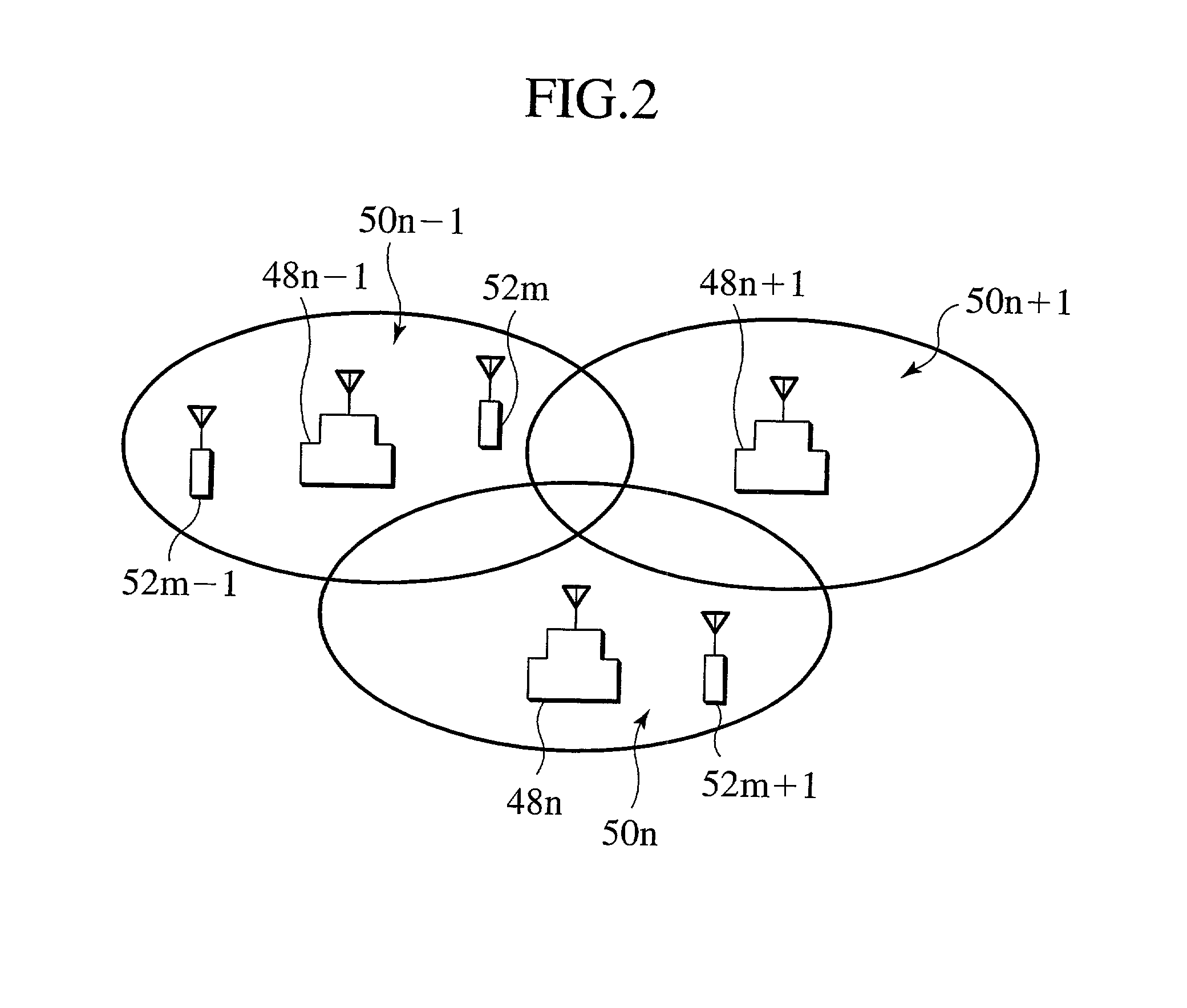
[0087] Next, a third embodiment of the present invention will be explained. The next generations of the wireless communication system are expected to support high speed signal transmission rates in the order of several Mbps to several tens of Mbps with a wider bandwidth exclusively occupied by each channel. Because of the limitation on the frequency resources as available, it is particularly important how to determine an effective arrangement of the respective cells in the cellular system.

[0088] FIG. 10 is a schematic diagram showing an example of the conventional cell arrangement in the case where only one frequency is available. As illustrated in FIG. 10, it is impossible to provide overlap between adjacent ones of the cells 92n-1, 92n and 92n+1 of base stations 90n-1, 90n and 90n+1. Accordingly, when the mobile station 94a in the cell 92n-1 is transiting to the position 94c through the position 94b, the communication between the mobile station 94a and either the...


PUM


Abstract

An improved transmitter apparatus, a receiver apparatus and a base station implemented with the transmitter and receiver apparatuses are described. These apparatuses and the base station serves to establish communication by making use of an orthogonal frequency division demultiplexing demodulation and an inverse spectrum spreading demodulation in combination. The communication coverage thereof can be expaned by making use of an orthogonal frequency division demultiplexing demodulation and an inverse spectrum spreading demodulation in combination.

Description

[0001] The subject application is related to subject matter disclosed in the Japanese Patent Application No. Heil2-54028 filed in Feb. 29, 2000 in Japan, to which the subject application claims priority under the Paris Convention and which is incorporated by reference herein.[0002] 1. Field of the Invention[0003] The present invention is related generally to a transmitter apparatus, a receiver apparatus and a base station implemented with the transmitter and receiver apparatuses which are communicated with each other by making use of an orthogonal frequency division demultiplexing modulation and a spectrum spreading modulation in combination.[0004] 2. Prior Art[0005] In recent years, it becomes an important issue to cope with interference due to delay spread through multipaths while the signal transmission rates of wireless communication systems have been increased. OFDM (Orthogonal Frequency Division Multiplexing) is a technique with which the problem of the interference due to del...

Claims


Application Information

Patent Timeline
IPC IPC(8): H04B7/08H04L1/00H04L5/02
CPCH04B7/086H04L1/0003H04L5/023
Inventor WAKUTSU, TAKASHI
Owner KK TOSHIBA
Learn More