Vehicle air conditioning system with seat air conditioning unit

Inactive Publication Date: 2001-09-20
DENSO CORP
View PDF0 Cites 29 Cited by
  • Summary
  • Abstract
  • Description
  • Claims
  • Application Information

AI Technical Summary

Problems solved by technology

Therefore, the seat air conditioning unit exercises an excessively high air conditioning ability in a steady state.
Consequently, the seat is cooled excessively in summer and is heated excessively in winter, and an uncomfortable feeling may be given to a passenger on the vehicle seat.
The foregoing problem is serious with a vehicle air conditioning system in which a seat air conditioning unit uses warm air or cool air supplied from a space air conditioning unit for seat heating or seat cooling.
Even if an air temperature level of the space air conditioning unit is in a steady state, an air temperature level (thermal sensation level) of the sea

Method used


Image

  • Vehicle air conditioning system with seat air conditioning unit
  • Vehicle air conditioning system with seat air conditioning unit
  • Vehicle air conditioning system with seat air conditioning unit

Examples


first embodiment

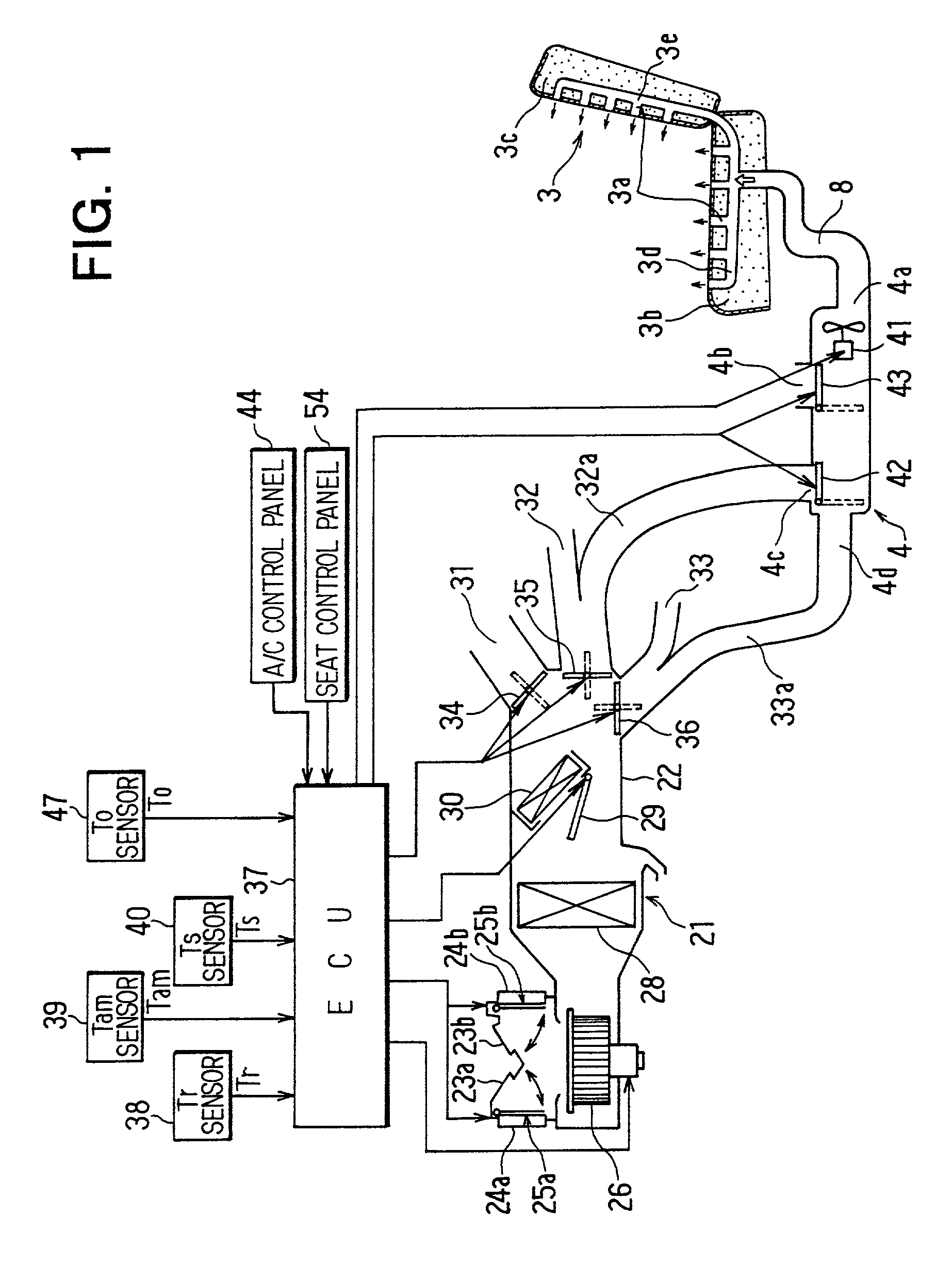
[0044] A vehicle air conditioning system according to the present invention will be described hereinafter with reference to FIGS. 1 to 10. First, a space air conditioning unit 21 will be described with reference to FIG. 1. An air duct 22 is provided with an outside air intake openings 23a and 23b for taking in outside air (fresh air) outside a passenger compartment and inside air inlets 24a and 24b for taking in inside air (air inside a passenger compartment at its upstream portion. An mixing amount ratio between inside air and outside air is adjusted by adjusting the respective positions of inside / outside air doors 25a and 25b.

[0045] A blower 26 is disposed in the air duct 22. An evaporator 28 of a refrigerant cycle system (not shown), an air mixing door 29 and a heater core 30 through which engine cooling water is circulated are disposed in the air duct 22 at a downstream air side of the blower 26, in this order. An air mixing ratio between air passing through the heater core 30 a...

second embodiment

[0143] A second preferred embodiment of the present invention will be now described with reference to FIGS. 13-22. In the second embodiment, a space air conditioning unit 100 can be applied to a vehicle having an engine for vehicle travelling or an electrical motor for vehicle travelling. The space air conditioning unit 100 is controlled by a space air-conditioning control unit (hereinafter, referred to as "space ECU") 102 so that a temperature of a passenger compartment can be maintained at a set temperature.

[0144] A seat air conditioning unit 104 is disposed under a front seat 103, for example, so that conditioned air of the space air conditioning unit 100 is introduced into the seat air conditioning unit 104. Components of the seat air conditioning unit 104 are controlled by a seat air-conditioning control unit (hereinafter, referred to as "seat ECU") 105 so that a thermal sensation feeling (level) of a seat surface of the front seat 103 can be always maintained at a desired ther...


PUM


Abstract

A vehicle air conditioning system includes a space air conditioning unit for blowing conditioned air into a passenger compartment, a seat air conditioning unit for blowing air into a vehicle seat, and a control unit for controlling the space air conditioning unit and the seat air conditioning unit. The control unit includes space controlling means for controlling the space air conditioning unit in accordance with a space control value calculated based on a space target air temperature, and seat controlling means for controlling the seat air conditioning unit in accordance with a seat control value calculated based on the space target air temperature. Further, the seat controlling means includes a first seat air conditioning means which determines the seat control value in a steady air conditioning state of the passenger compartment, and a second seat air-conditioning means which determines the seat control value in a transition air-conditioning state of the passenger compartment.

Description

[0001] This application is related to and claims priority from Japanese Patent Applications No. 2000-20073 filed on Jan. 28, 2000, No. 2000-95021 filed on Mar. 30, 2000, No. 2000-264860 filed on Sep. 1, 2000, and No. 2000-339037 filed on Nov. 7, 2000, the contents of which are hereby incorporated by reference.[0002] 1. Field of the Invention[0003] The present invention relates to a vehicle air conditioning system including a space air conditioning unit that introduces conditioned air into a passenger compartment, and a seat air conditioning unit that introduce air into a vehicle seat.[0004] 2. Description of the Related Art[0005] In a conventional vehicle air conditioning system disclosed in JP-A-10-297243, a seat air conditioning unit and a space air conditioning unit are provided. Further, a control unit is provided to change an operating condition or a set information of the space air conditioning unit based on a seat temperature of a vehicle, an operating condition of the seat a...

Claims


Application Information

Patent Timeline
IPC IPC(8): B60H1/00B60N2/56
CPCB60H1/00285B60N2/5628B60N2/5657Y10S454/907
Inventor AOKI, SHINJIYOSHINORI, TAKESHISAKAI, KOJIKAJINO, YUICHI
Owner DENSO CORP
Why Eureka
Try Eureka