Torsional vibration damper

a torsional vibration and damper technology, applied in the direction of yielding couplings, mechanical devices, couplings, etc., can solve the problems of stress cracks or ruptures of high temperature rise, and increase the cost of producing the flywheel mass elemen

Inactive Publication Date: 2001-10-04
MANNESMANN SACHS AG
View PDF0 Cites 18 Cited by
  • Summary
  • Abstract
  • Description
  • Claims
  • Application Information

AI Technical Summary

Problems solved by technology

However, the following problems occur when such a material is selected: in certain operating situations, for example, when ascending a grade with a trailer, a very high rise in temperature can come about within a short time at the friction surface of the flywheel mass element, whereas the opposite side, i.e., the side of the flywheel mass element remote of the friction surface, is hardly heated.
This results in a large heat gradient in axial direction inside the flywheel mass element which leads to very high internal stresses that can result in stress cracks or rupturing of the flywheel mass element.
In order to prevent this, it is necessary to use high-quality cast materials which increases the cost of producing the flywheel mass element.
Further, the construction of the flywheel mass element as a cast structural component part has the disadvantage that reworking or after-machining of the cast structural component part, for example, for arranging fastening bore holes, possibly threaded, or for forming cooling ribs on the back of the flywheel mass element remote of the friction surface, is very time-consuming and therefore costly.

Method used


Image

  • Torsional vibration damper
  • Torsional vibration damper
  • Torsional vibration damper

Examples


Embodiment Construction

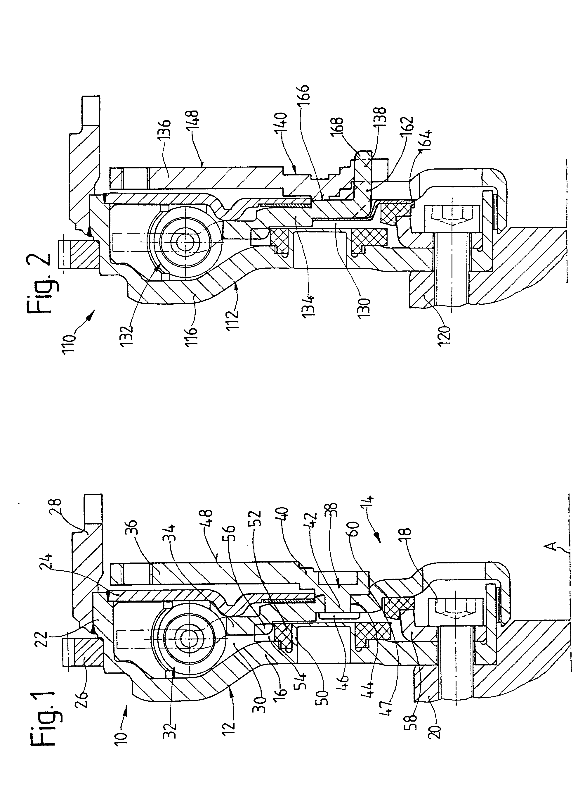
[0054] FIG. 1 shows a torsional vibration damper 10 according to the invention. This torsional vibration damper 10 comprises a primary side 12 and a secondary side 14 which are rotatable relative to one another about an axis of rotation A. The primary side 12 comprises a substantially disk-shaped first transmission part 16 which is arranged at a drive shaft 20 on the radial inner side by a plurality of fastening screws 18. On the radial outer side, the first transmission part 16 has an annular portion 22, extending substantially in axial direction, to which a disk element 24 which extends radially inward is connected by welding. Further, a starter ring gear 26 and an additional mass element 28 are arranged at the axial portion 22. The first transmission part 16 and the disk element 23 together form a hollow space 30 which is tightly closed toward the radial outer side and in which a damper element arrangement 32 which has at least one spring unit and which is filled with a viscous m...


PUM


Abstract

A torsional vibration damper, particularly for a drivetrain in a motor vehicle, having a substantially disk-shaped flywheel mass element having a friction surface for cooperating with friction facings of a friction clutch and a damper element arrangement communicating with the flywheel mass element, wherein the flywheel mass element is produced from a sheet metal material.

Description

[0001] 1. Field of the Invention[0002] The present invention is directed to a torsional vibration damper, particularly for a drivetrain in a motor vehicle, comprising a substantially disk-shaped flywheel mass element having a friction surface for cooperating with friction facings of a friction clutch and a damper element arrangement communicating with the flywheel mass element.[0003] 2. Description of the Related Art[0004] A torsional vibration damper of the type mentioned above is known from U.S. Pat. No. 5,669,478. In this torsional vibration damper, the flywheel mass element is made from cast material. However, the following problems occur when such a material is selected: in certain operating situations, for example, when ascending a grade with a trailer, a very high rise in temperature can come about within a short time at the friction surface of the flywheel mass element, whereas the opposite side, i.e., the side of the flywheel mass element remote of the friction surface, is ...

Claims


Application Information

Patent Timeline
Patent Type & Authority Applications(United States)
IPC IPC(8): F16F15/131F16F15/14
CPCF16F15/1315F16F15/145
Inventor SCHAUDER, BENEDIKTSCHIERLING, BERNHARDKLEIFGES, JURGEN
Owner MANNESMANN SACHS AG
Why Eureka
Try Eureka