Underwater detection apparatus

a technology of underwater detection and underwater equipment, which is applied in the direction of transducer details, electrical transducers, instruments, etc., can solve the problems of increasing equipment cost and mechanical size of fish finders, and achieve the effect of simplifying manufacture and inventory control

Inactive Publication Date: 2001-10-04
FURUNO ELECTRIC CO LTD
View PDF0 Cites 21 Cited by
  • Summary
  • Abstract
  • Description
  • Claims
  • Application Information

AI Technical Summary

Benefits of technology

0013] Another object of the invention is to provide an underwater detection apparatus which simplifies manufacture and inventory control of fish finders, and the like.

Problems solved by technology

Provision of the two-channel transmitting and receiving circuits, however, results in an increase in the mechanical size of the fish finder as well as in equipment cost.

Method used


Image

  • Underwater detection apparatus
  • Underwater detection apparatus
  • Underwater detection apparatus

Examples


first embodiment

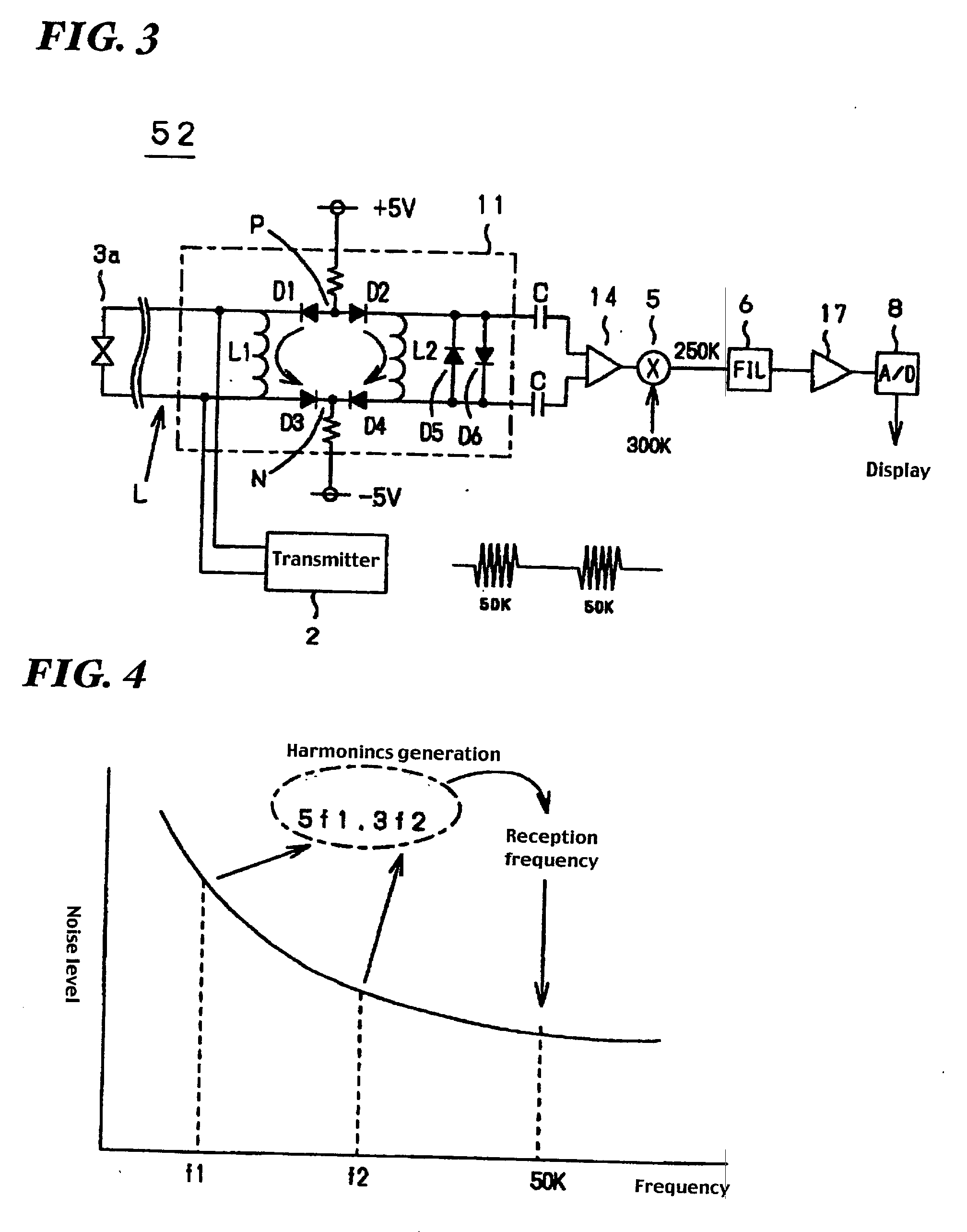
[0038] FIG. 3 is a block diagram of a fish finder 52 according to the invention, in which elements equivalent to those shown in FIG. 1 are designated by the same reference numerals. The fish finder 52 employs a trap circuit 11 having connecting points P, N on two lines L. Anodes of diodes D1, D2 are connected to the connecting point P while cathodes of diodes D3, D4 are connected to the connecting point N.

[0039] A coil L1 is connected between a cathode of the diode D1 and an anode of the diode D3, and a transducer 3a is connected between both ends of the coil L1. Also, a coil L2, as well as two diodes D5, D6 connected in parallel but in opposite directions, are connected between a cathode of the diode D2 and an anode of the diode D4.

[0040] The cathode of the diode D2 and the anode of the diode D4 are connected to input terminals of a preamplifier 14 in a succeeding stage through respective capacitors C. It is to be noted that the cathode of the diode D2 and the anode of the diode D4...

second embodiment

[0051] FIG. 6 is a block diagram of a fish finder 53 according to the invention, in which elements equivalent to those shown in FIG. 3 are designated by the same reference numerals. Two transducers 3b, 3a having operating frequencies of 15 kHz and 50 kHz, for example, arranged in parallel are connected to a broadband trap circuit 11 through a low-pass filter 21 and a high-pass filter 22, respectively. The low-pass filter 21 and the high-pass filter 22 constitute typical inductance-capacitance (LC) circuits as shown in FIG. 7.

[0052] A transmitting signal S output from a transmitter 23 contains 15 kHz and 50 kHz components. This is because 15 kHz and 50 kHz signals are alternately supplied from oscillators 25b and 25a, respectively, to the transmitter 23 via a switch 24. The 15 kHz and 50 kHz components are separated from each other by the low-pass filter 21 and the high-pass filter 22 and, as a consequence, a 15 kHz transmitting signal is fed into the 15 kHz transducer 3b while a 50 ...

third embodiment

[0055] FIG. 8 is a block diagram of a fish finder 54 according to the invention, in which elements equivalent to those shown in FIG. 6 are designated by the same reference numerals. Unlike the fish finder 53 of FIG. 6, this fish finder 54 does not incorporate the low-pass filter 21 or the high-pass filter 22. Instead, a 15 kHz transducer 3c and a 50 kHz transducer 3d arranged in parallel are connected directly to a broadband trap circuit 11.

[0056] In this embodiment, the transducer 3c has a low impedance at its operating frequency of 15 kHz and a high impedance at 50 kHz, whereas the transducer 3d has a low impedance at its operating frequency of 50 kHz and a high impedance at 15 kHz.

[0057] As is the case with the fish finder 53 of FIG. 6, transmission signals containing 15 kHz and 50 kHz components occurring in successive turns are supplied from a transmitter 23 to the broadband trap circuit 11. While both the 15 kHz and 50 kHz signal components are delivered to the transducers 3c ...


PUM


Abstract

An underwater detection apparatus comprises a transducer, a transmitter capable of generating transmitting signals of a plurality of respective frequencies and for generating a transmitting signal, a broadband trap circuit for transferring the transmitting signal fed from the transmitter to the transducer and for passing an echo signal fed from the transducer, a preamplifier for amplifying the echo signal fed from the broadband trap circuit, a mixer for converting an output of the preamplifier into a signal of a specific frequency, a filter for selectively passing the signal of only the specific frequency-band output from the mixer, a main amplifier for amplifying an output of the filter, an A/D converter for converting an output of the main amplifier into a digital form, and a display circuit for displaying the digitized output of the A/D converter on a monitor, wherein the preamplifier is of a low-gain type.

Description

BACKGROUND OF THE INVENTION AND RELATED ART STATEMENT[0001] The present invention relates to ultrasonic underwater detection apparatuses.[0002] The invention will be explained as embodied in a fish finder installed in a ship, for detecting underwater conditions beneath the own ship.[0003] FIG. 1 is a general block diagram of a conventional fish finder 51 comprising one transmit-receive channel. The fish finder is generally used in a bad environment having various background noises such as a ship's running noise and noises produced in the ship. A trap circuit 1 supplies a 50 kHz transmitting burst signal S fed from a transmitter 2 to a transducer 3a and delivers a received echo signal fed from the transducer 3a to a preamplifier 4.[0004] The transducer 3a is connected to the trap circuit 1 by means of two electric conductors. The length of the two electric conductors is, for example, more than five meters depending on the size of the own ship. The received echo signal from the transd...

Claims


Application Information

Patent Timeline
Patent Type & Authority Applications(United States)
IPC IPC(8): G01S7/526H04R3/00G01S15/10G01S15/96
CPCG01S15/107G01S15/96Y10S367/903Y10S367/908
Inventor INOUCHI, MITSUHIRO
Owner FURUNO ELECTRIC CO LTD
Why Eureka
Try Eureka