
Battery connector

a technology of battery connectors and connectors, which is applied in the direction of coupling contact members, coupling device connections, electric discharge lamps, etc., can solve the problems of poor electrical contact and hiccups in smooth plug mating, and achieve the effect of smooth insertion of electrical connectors

Inactive Publication Date: 2001-10-25
MOLEX INC
View PDF0 Cites 42 Cited by
  • Summary
  • Abstract
  • Description
  • Claims
  • Application Information

AI Technical Summary

Benefits of technology

[0007] An object of the present invention is to provide an electrical connector which can achieve smooth insertion of the electrical connector.
[0008] Another object of the present invention is to provide an electrical connector which can increase the normal contact force of the terminals.
[0009] A further object of the present invention is to provide an electrical connector which can effectively prevent poor electrical contact.

Problems solved by technology

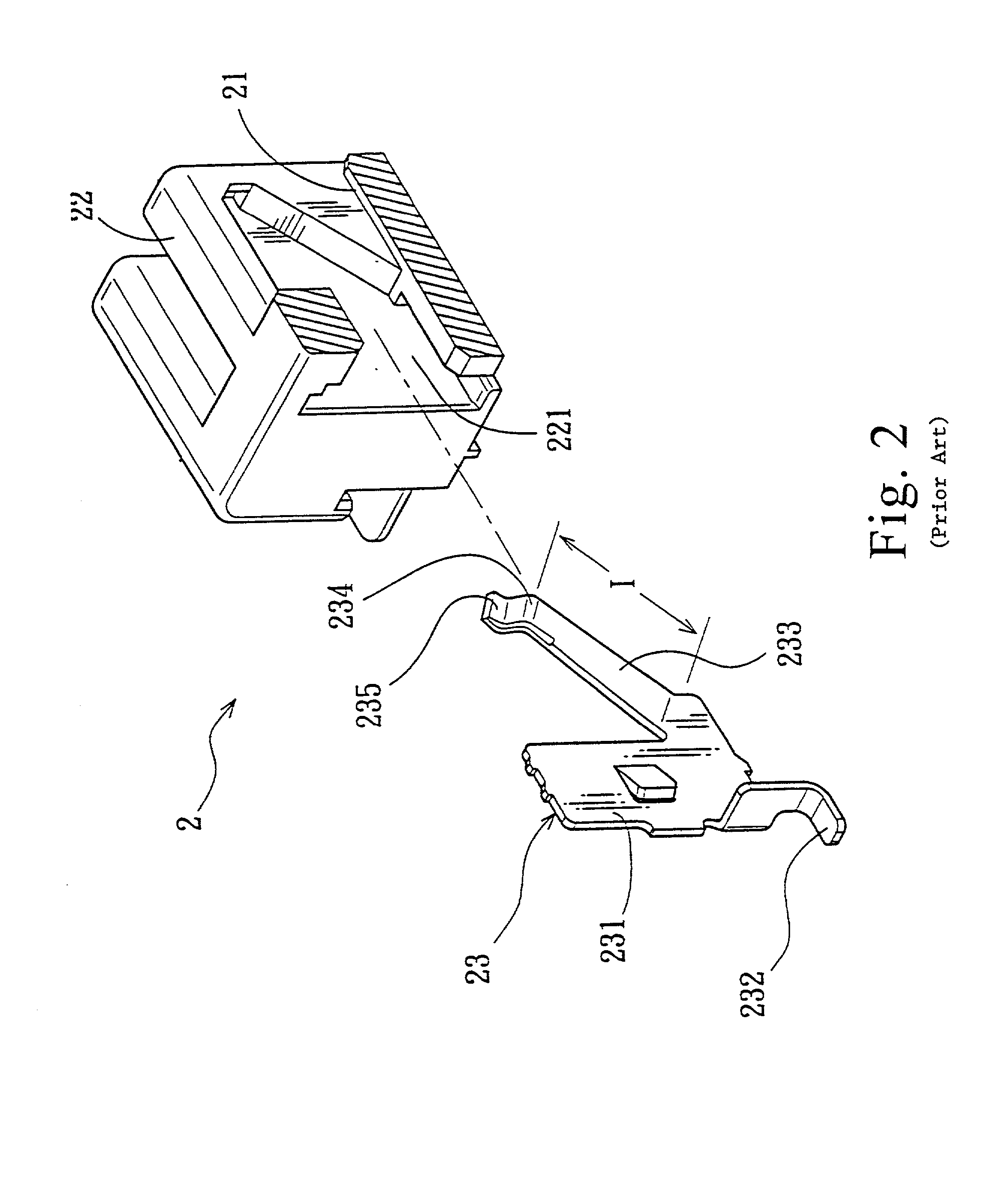
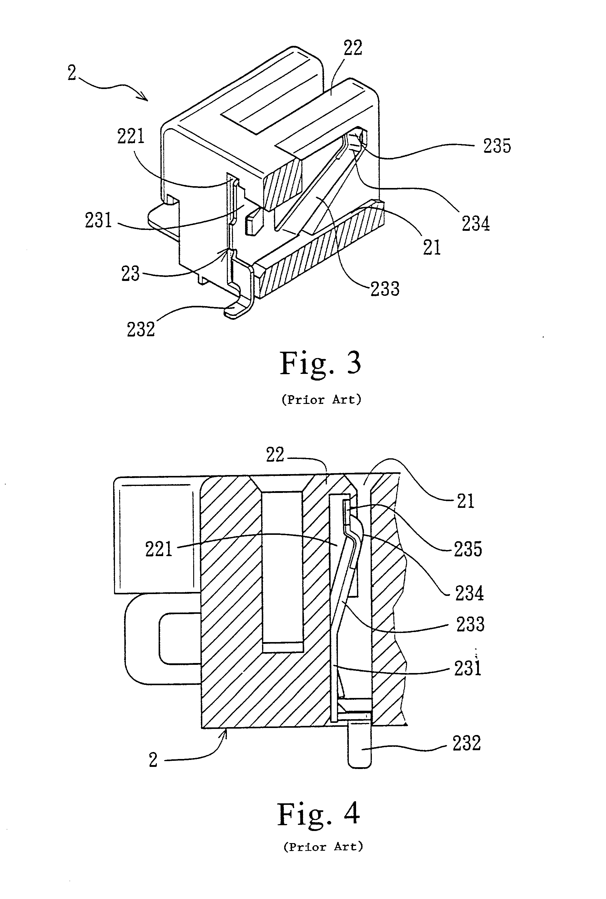
1. Obstructed insertion. Since the resilient arm 233 of the terminal 23 extends from the inside to the outside (i.e., from the rear to the front), which is opposite to the direction of insertion of the metal blade terminal 11 of the plug connector 1 into the insert groove 21 from the outside to the inside, once the metal blade terminal 11 enters the insert groove, it is obstructed by the contact portion 234 projecting from the terminal 23 into the insert groove 21 and cannot advance any further. Therefore, a greater force has to be applied in order to continue pushing of the blade terminal 11 onward, thereby hindering smooth mating of the plug connector 1 with the socket connector 2.
2. Weak normal contact force of the terminal. Since the length (I) of the resilient arm 233 of terminal 23 must be sufficient in order for the contact portion 234 to be in the vicinity of the front end portion of the insert groove 21 to facilitate connection of metal blade terminals 11 of the plug connector 1, the length (I) of the resilient arm 233 is relatively long. Since the arm of force of the resilient arm 233 is relatively long, i.e., the distance of the contact portion 234 from its fulcrum point is relatively long, the normal contact force of the contact portion 234 will be decreased with an increase in the length of the arm of force. Furthermore, as the length of the resilient arm 233 is relatively long and as the width of the insert groove 21 is fixed, the amount of displacement of the contact portion 234 toward the receiving groove 221 when pushed by the metal insert plate 11 is limited. Therefore, the normal contact force produced upon the displacement of the resilient arm 233 when the resilient arm 233 is pushed is likewise small. Hence, it is likely that the contact portion 234 cannot maintain good contact with the metal blade terminals 11, thereby resulting in poor electrical contact.

Method used


Image

  • Battery connector
  • Battery connector
  • Battery connector

Examples


Embodiment Construction

[0032] The socket insulating housing 3 has a body 31. Two side plates 32 and a plurality of spacer plates 33 disposed between the two side plates 32 extend forwardly from the body 31 in a spaced-apart and juxtaposed arrangement such that a retaining groove 34 is defined between each side plate 32 and the adjacent spacer plate 33 for mating with and positioning another battery connector (i.e., a plug connector) during coupling of the battery connectors. The insulating housing 3 further has a plurality of terminal receiving portions 35. Each of the terminal receiving portions 35 includes a first insert groove 351 and a second insert groove 352 communicated with the first insert groove 351. With reference to FIG. 6, the first insert groove 351 is provided between adjacent spacer plates 33 of the insulating housing 3, and is formed by recessing a wall surface 331 of the left spacer plate 33 facing the right spacer plate 33 until the insert groove 351 extends to a mounting face 36 of the...


PUM


Abstract

An electrical connector is provided which includes an insulating housing having at least one terminal receiving portion formed by a first insert groove and a second insert groove communicated with the and first a second insert groove, and a conductive terminal received in said at least one terminal receiving portion and including a body, a connecting arm, a connecting portion and a conducting portion. The second insert groove has a first end. The body is located in the first insert groove, and has a first side and a second side opposite to the first side. The connecting extends transversely from the second side of the body in a direction distal to the first side of the body. The connecting portion extends from the first side of the body in a direction distal to the second side of the body, and can achieve electrical connection with a circuit board. The conducting portion extends upwardly from a free end of the connecting arm into the second insert groove. The conducting portion includes a guiding portion which extends from the second insert groove to the first insert groove and which is proximate to the first end of the second insert groove, and a contact portion which is farther away from the first end than the guiding portion such that the conducting portion can achieve electrical contact with a matching terminal inserted via the first end of the second insert groove into the second insert groove. Thus, insertion of the electrical connector is smooth; the normal contact force of the conductive terminal can be increased; and poor electrical contact can be effectively prevented.

Description

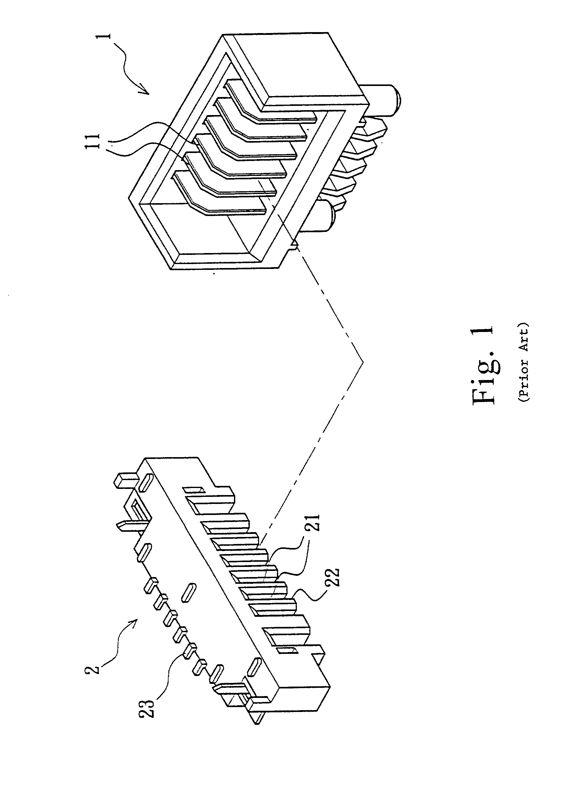
FIELD OF THE INVENTION[0001] The present invention provides a battery connector more particularly a battery connector with terminals capable of providing a relatively large normal contact force.BACKGROUND OF THE INVENTION[0002] Battery connectors are adapted for interconnecting an electrical device and a battery. FIG. 1 shows a conventional battery connector that includes a plug connector 1 and a socket connector 2 for matching the plug connector 1. The plug connector 1 is generally secured on a circuit board of an electrical device (such as the mother board of a notebook computer) and the socket connector 2 is provided at an output end of a battery. The plug connector 1 has a plurality of spaced-apart juxtaposed metal blade terminals 11. The socket connector 2 is provided with a plurality of insert grooves 21 corresponding to the metal blade terminals 11. The insert grooves 21 are defined by a plurality of juxtaposed spacer plates 22 that are spaced apart from each other. Each of t...

Claims


Application Information

Patent Timeline
Patent Type & Authority Applications(United States)
IPC IPC(8): H01R13/26
CPCH01R13/26
Inventor CHIANG, CHUN-HSIANG
Owner MOLEX INC
Learn More