Glulam wood beams and method of making same

a technology of glue and wood beams, applied in the field of wood beams, can solve the problems of difficult glueing of planks, difficult to reach objects, and tendency to change shape upon drying, and achieve the effect of increasing mechanical stability

Inactive Publication Date: 2001-11-01
MATHIS TECH
View PDF0 Cites 9 Cited by
  • Summary
  • Abstract
  • Description
  • Claims
  • Application Information

AI Technical Summary

Benefits of technology

0058] As illustrated in FIG. 8, it is possible to obtain strips with dispersed finger joints using beams assembled according to the method of the instant invention. The beam is cut along a longitadinal axis 81 perpendicular to the finger joints 40 and in such a way that the axis defining the cutting line does

Problems solved by technology

This objective is particularly difficult to reach when the trees are of small diameter.
Furthermore, the planks with greater width generally used in the preparation of glulam wood beams are made with trunks exhibiting large diameter and they have the tendency to change shape upon drying.
This property renders the glueing of the p

Method used


Image

  • Glulam wood beams and method of making same
  • Glulam wood beams and method of making same
  • Glulam wood beams and method of making same

Examples


example 1

Precomposition of individual strips panels

[0060] A. Individual strips

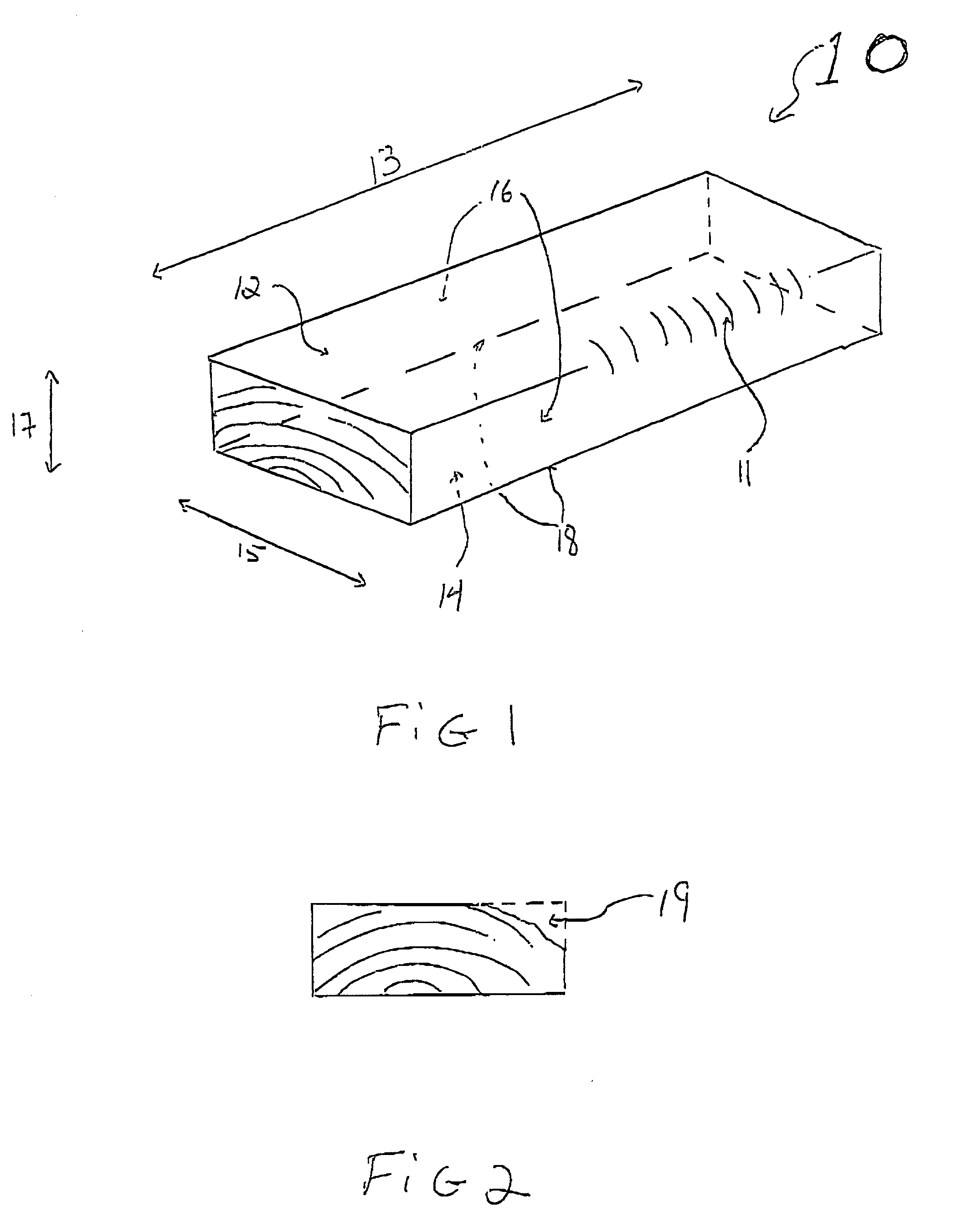
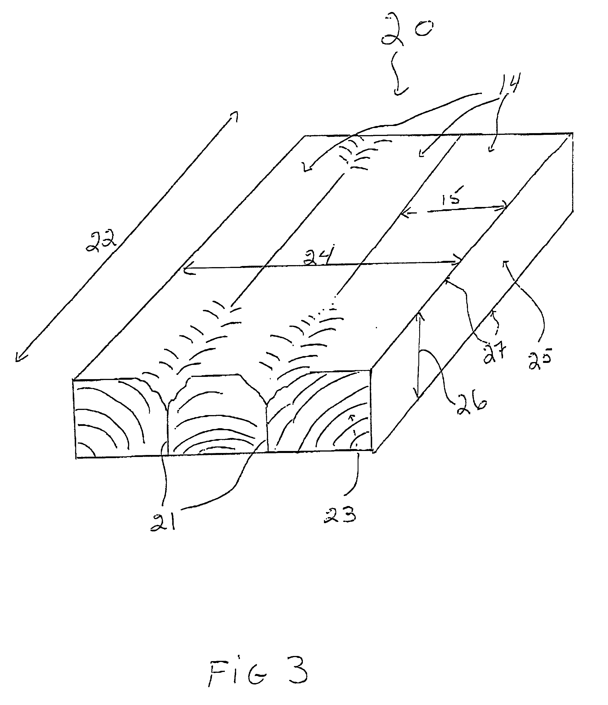
[0061] A strip of a width of twelve inches (273 mm) may be obtained by assembling three planks with three two by four (2".times.4") planks. The sides of the two planks located at the lateral ends of the strips form sharp edges (devoided of flash) with the top and the bottom of the planks.

[0062] Panels

[0063] A width of thirteen inches (289 mm) may be obtained by assembling planks into panels that are then cut at the appropriate position. For example, the panel may be composed of one 2".times.4" plank, three 2".times.3" planks, etc. The cutting of the panel into strips is accomplished by cutting the 2".times.4": pls at a position X.sub.0 and X.sub.1 according to the method described above to obtain a strip with a width of thirteen inches.

example 2

Assembly of beams of various width using planks of various width

[0064] The following table presents the width of beams that can be obtained using strips comprising 2".times.3", 2".times.4" and 2".times.6" planks. The table also contains information on the loss of material during the manufacture of the beams. Also shown is the ratio of original wood material necessary to produce one metre cubed of finished products as well as the width of beams available on the market.

1TABLE Finished product ratio starting beam dimension Lost of material material (m.sup.3 beam dimension (inches and mm) of (m.sup.3 finished product for starting material (inches) available the instant Recurring 1 m.sup.3 of starting material) for 1 m.sup.3 finished commercially invention of beams Length Cutting Planing product 2 1 / 2 2 1 / 8 54 MM 1 / 4 strip B 0,9 0,685 0,948 1,711 3 3 1 / 8 3 1 / 8 79,3 MM 1 / 3 strip A 0,9 0,75 0,953 1,555 3 1 / 2 3 1 / 2 88,9 MM 1 / 3 strip E 0,9 0,785 0,959 1.555 4 1 / 8 105 MM strip D 5 4 7 / 8 122,5...

example 3

Examples of beams comprising flash according to the instant invention

[0072] The models of beams described below will be better understood by referring to FIGS. 10-15.

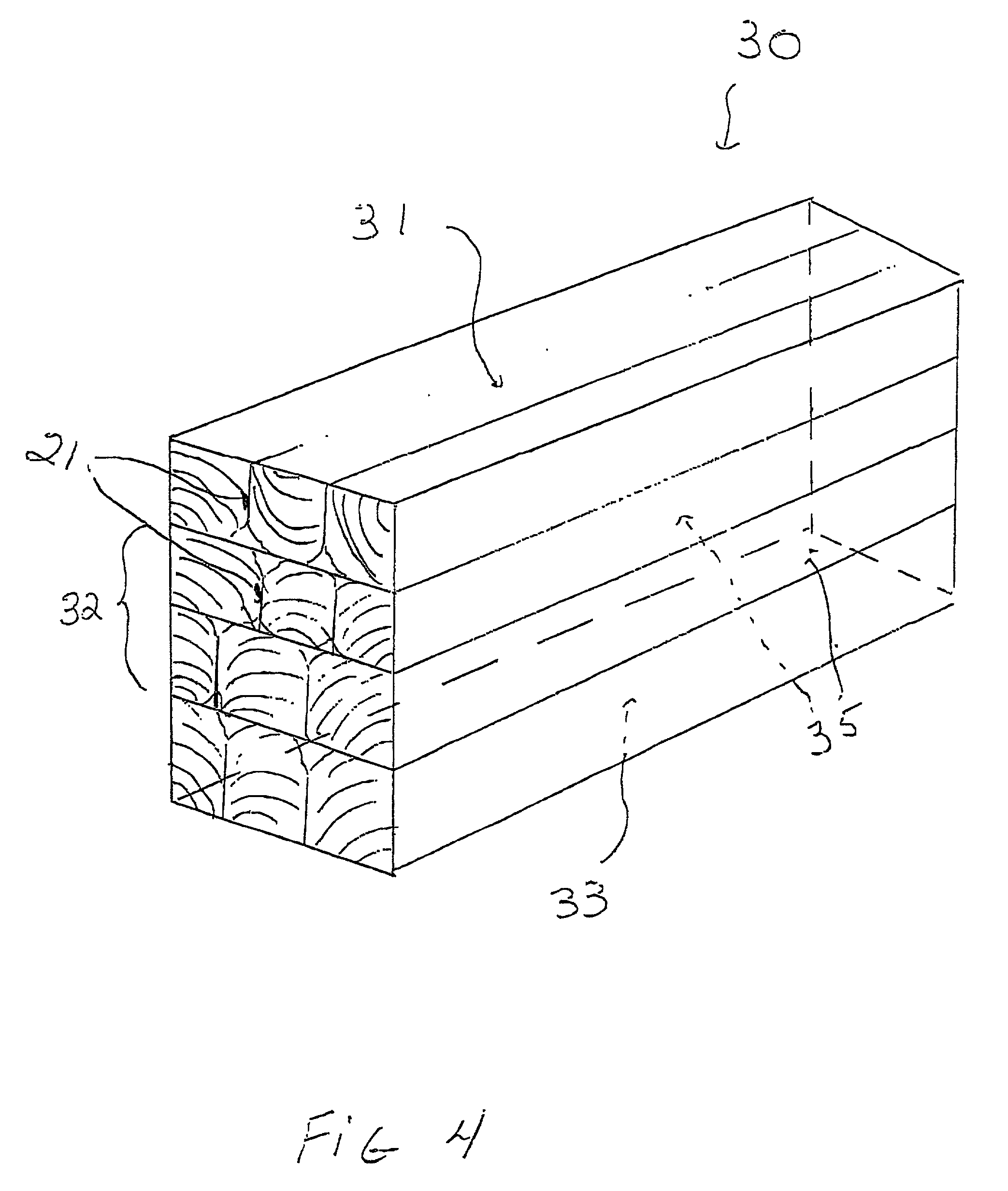
[0073] A. In the beam of FIG. 10, the central part 101 comprises individual squared planks having a width equal to the width of the strip of the top and bottom strips of the beam.

[0074] B. The beam of FIG. 11 is formed by two strips 111 vertically adhered and in which the lateral joints of the central part are out of line.

[0075] C. The beam illustrated in FIG. 12 is composed of three strips 121 vertically adhered and in which the later joints of the central part are substantally co-linear.

[0076] D. The beam illustrated in FIG. 13 is composed of three strips 131 vertically adhered and in which the lateral joints forming the central part are co-linear. The top and the bottom part of the beam are formed by strips devoided of flash and being optionally reinforced with fiberglass, carbon or airmide bands. In addition, the wi...


PUM


Abstract

There is provided a glulam wood beam comprising planks having a width substantially smaller than The width of the beam, assembled into snips. The beam is characterized by the presence of flash in the interior by external surfaces made essentially of duramen. There is further provided a method for making the wood beam of the instant invention wherein the strips are derived from panels and in which the cutting of the panels into strips is programmed to ensure that the subsequent assembly of the strips will result in beams having external surfaces comprised essentially of duramen, thus providing a beam with enhanced mechanical resistance.

Description

[0001] Conventional, glulam wood beams manufacturing are usually manufactured with perfectly squared wood planks corresponding to the width of the desired beam less the wood necessary to plane down the beam so as to obtain perfectly smooth surfaces,[0002] The planing down step is often necessary in view of the fact that the glulam beams can be used as decorating elements as well as structural elements. This double use of glulam beans requires that the surface be exempt of any defects such as the presence of flash on the planks.[0003] On the other hand, an optimum exploitation of forest resources requires that saw mills exact as much squad planks as possible. This objective is particularly difficult to reach when the trees are of small diameter. In this case, the proportion of planks with bark can be important since the diameter of the tree is sometimes insufficient to provide planks of standard dimensions to produce perfectly squared surfaces. However, this type of tree with small t...

Claims


Application Information

Patent Timeline
IPC IPC(8): B27M3/00E04C3/14
CPCB27M3/0053E04C3/14
Inventor MATHIS, PAUL-HENRI
Owner MATHIS TECH
Why Eureka
Try Eureka