Method and apparatus relating to radio communication

a radio communication and apparatus technology, applied in the field of radio communication, can solve the problems of communication loss, cdma methods are somewhat more complicated than fdma and tdma, and radio terminals are not allowed to use the first frequency band for uplink communication

Inactive Publication Date: 2001-11-15
HIGHBRIDGE PRINCIPAL STRATEGIES LLC AS COLLATERAL AGENT
View PDF2 Cites 22 Cited by
  • Summary
  • Abstract
  • Description
  • Claims
  • Application Information

AI Technical Summary

Problems solved by technology

However, the radio terminal is not allowed to use the first frequency band for uplink communication all the time, but only during predetermined time intervals--so called time slots.
The CDMA methods are somewhat more complicated than FDMA and TDMA.
However, there are several known transmission problems that may cause communications to be lost and communication quality to be degraded.
Some of the main transmission problems are path loss (i.e. a decreased signal strength due to an increased distance between the radio terminal and the radio base station), interference from other radio transmissions and Rayleigh fading (i.e. decreased signal strength due to destructive interference caused by multipath propagation of radio signals).
When interference is present, the received signal strength (on up-and / or downlink) is normally not low but the communication quality is nevertheless poor, e.g. the bit error rate (BER) and / or frame erasure rate (FER) are high.
Inter-cell handoff is therefore not a suitable remedy, since low signal strength is not the problem.
For stationary and slow moving radio terminals Rayleigh fading is more likely to cause the loss of communications or severely degraded communication quality, especially in FDMA and TDMA systems.
However, in indoor environments the coherence bandwidth is normally large, and Rayleigh fading may therefore influence also band spread signals negatively to a non-negligible extent.

Method used


Image

  • Method and apparatus relating to radio communication
  • Method and apparatus relating to radio communication
  • Method and apparatus relating to radio communication

Examples


Embodiment Construction

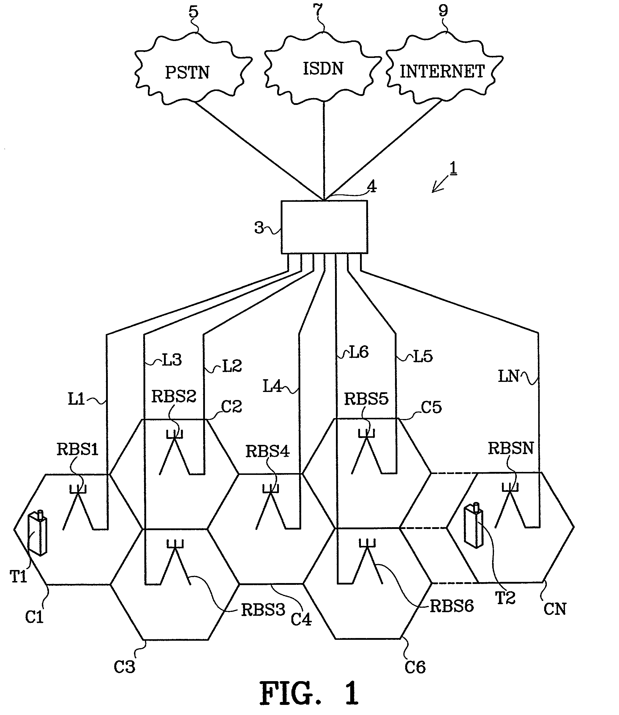
[0026] FIG. 1 is a block diagram describing a PLMN 1 comprising a land system having a switching system 3 and a number (N) of radio base stations RBS1-RBSN. In this example the radio base stations RBS1-RBSN are arranged for providing radio communication services (e.g. speech communication or data communication) in corresponding cells C1-CN. The radio base stations RBS1-RBSN are connected to the switching system 3 by means of communication links L1-LN. In this example, the communication links L1-LN are landline connections. Alternatively, however, the communication links L1-LN are provided in some other form, e.g. in the form of radio links. The switching system includes a gateway node 4, which connects the PLMN 1 to other networks--in this example a PSTN 5, an ISDN 7 (Integrated Services Digital Network) and Internet 9. Radio terminals have subscriptions registered in the switching system 3. By way of example, a first radio terminal T1 is currently present in the cell C1 associated ...


PUM


Abstract

The present invention pertains to the field of methods and apparatuses relating to radio communication; and in particular to the part of this field that concerns cellular radio communication. The present invention addresses mainly the problem of improving reliability and communication quality in a cellular radio communication system (1). According to the invention, it is determined whether one of an uplink (25) or a downlink (25) of a radio channel (23) is subject to a Rayleigh fading dip. If it is determined that one of the uplink (25) or the downlink (27) is subject to a Rayleigh fading dip, it is then determined whether it is necessary to execute a countermeasure in order to avoid the negative influences of Rayleigh fading on the channel (23). The invention is not limited to improving conditions on one channel but may be employed to any number of channels used for communications in the cellular radio communication system (1).

Description

[0001] The present invention pertains to the field of methods and apparatuses relating to radio communication; and in particular to the part of this field that concerns cellular radio communication.BACKGROUND AND RELATED ART[0002] A conventional public land mobile telephone network (PLMN)--i.e. cellular radio communication system--include a land system and one or more radio terminals, e.g. mobile (or fixed) cellular radio phones, cellular communicators or computers having associated cellular radio communication equipment. The land system typically includes a switching system, which is connected to one or more radio communication nodes, commonly referred to as radio base stations (RBS). The switching system includes one or more switching nodes, for example mobile services switching centres (MSC), which are arranged for providing the necessary switching functions in order for information (e.g. coded speech or data) to be transferred in a desired manner between the radio base stations....

Claims


Application Information

Patent Timeline
Patent Type & Authority Applications(United States)
IPC IPC(8): H04B1/707H04B7/26H04B17/00H04L1/00
CPCH04B1/7115H04B17/309H04L1/20H04B7/2628
Inventor SIMONSSON, ARNESTROMSOE, MIKAEL
Owner HIGHBRIDGE PRINCIPAL STRATEGIES LLC AS COLLATERAL AGENT
Why Eureka
Try Eureka