
Compound plasma configuration, and method and apparatus for generating a compound plasma configuration

a plasma configuration and configuration technology, applied in the direction of nuclear reactors, greenhouse gas reduction, nuclear explosives, etc., can solve the problems of increasing the energy and temperature of the kernel, and inefficiently applying a large amount of energy simultaneously

Inactive Publication Date: 2001-11-29
KOLOC PAUL M
View PDF0 Cites 11 Cited by
  • Summary
  • Abstract
  • Description
  • Claims
  • Application Information

AI Technical Summary

Problems solved by technology

As a result the kernel may exist for a period of time during which its energy losses are limited to high temperature radiation to the mantle.
However, compression of the mantle will force compression of the poloidal field, and will result in increasing the energy and temperature of the kernel.
If a gas or liquid is used to apply fluid pressure to the mantle, particles will diffuse through and penetrate the mantle, however, these particles will become ionized as they are exposed to the intense heat radiated by the kernel.
However, this method inefficiently applied a large amount of energy simultaneously to a substantial volume of the media in which the PMK would be formed.
Consequently, the energy applied to each small volume of the region was reduced, and thus the effective energizing of the media was slower and required more time.
As noted, these previous processes were somewhat unreliable.
Furthermore, an apparatus necessary to generate a PMK in this fashion is rather complex, requiring a separate power source for generating a helical ionized region in the gas, such as a plasma gun or a flash lamp, in addition to a high voltage source for passing current through the ionized region.
Furthermore, this apparatus is quite inductive from the outset, due to its size, thus retarding the rise time of the current at initiation.
The compound plasma configuration produced by these earlier methods also lacked in total lifetime and stability.
However, because of the very short lifetime (1 microsecond) of the initially merged ring, the very strong compressional energizing of the plasma could not extend fusion reaction times sufficiently to generate a break even fusion burn.
However, this may sacrifice source life; the magnetic stress can be quite high since the helical conductor will suffer net strong radial compression.
However, this increases the inductance and slows down the current pulse.
In contrast, the previous devices deposited their energy across a large volume, resulting in low power density.
Furthermore, the strength and direction of the beams may be affected by the geometry of the mantle, the size and age of mantle, and the amount and type of the impurities incorporated into the compound plasma configuration.
This may excite nitrogen gas, causing florescence, when embedded in a blanket fluid containing this gas.

Method used


Image

  • Compound plasma configuration, and method and apparatus for generating a compound plasma configuration
  • Compound plasma configuration, and method and apparatus for generating a compound plasma configuration
  • Compound plasma configuration, and method and apparatus for generating a compound plasma configuration

Examples


Embodiment Construction

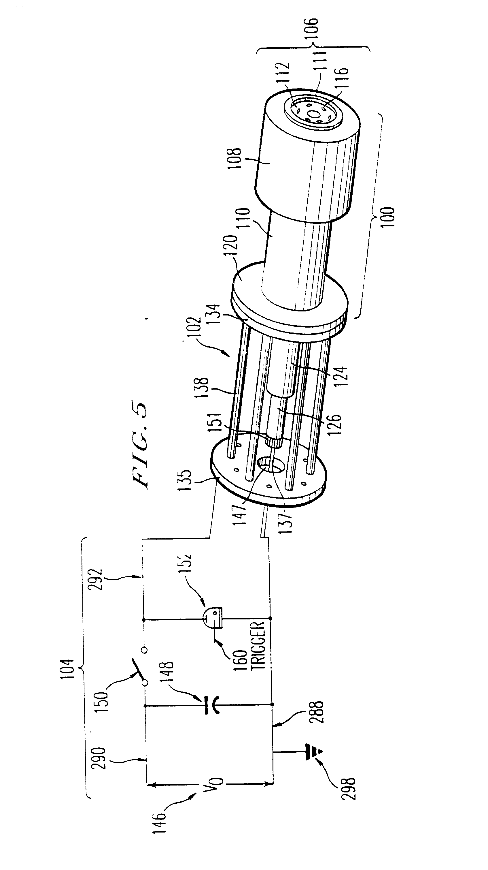
[0098] The following is an example of an inexpensive working device. The conducting cylinder is composed of 5 / 8" copper tubing while the helical conductor is composed of lengths of single strand 12-gauge copper electrical wire. A half-inch insulating fiberglass reinforced thin-walled plastic tube #124 which extends the full length of the distance between the annular electrode plane and the connecting rod acts as an insulating spacer between conducting cylinder and helical conductor. A vacuum potable epoxy fills the space within insulating tube and thus embeds the helical conductor. The insulating material on the 12-gauge electrical wires is excellent as a spacer between the multiple elements in the helical conductor, while the wires in the axial bundle are stripped over the length which is inserted and brazed into the connector rod. The connector rod is composed of a 3 / 8" brass plumbing stud. The insulating stress support cylinder which fits snugly over the conducting cylinder is a ...


PUM


Abstract

A compound plasma configuration can be formed from a device having pins, and an annular electrode surrounding the pins. A cylindrical conductor is electrically connected to, and coaxial with, the annular electrode, and a helical conductor coaxial with the cylindrical conductor. The helical conductor is composed of wires, each wire electrically connected to each pin. The annular electrode and the pins are disposed in the same direction away from the interior of the conducting cylinder.

Description

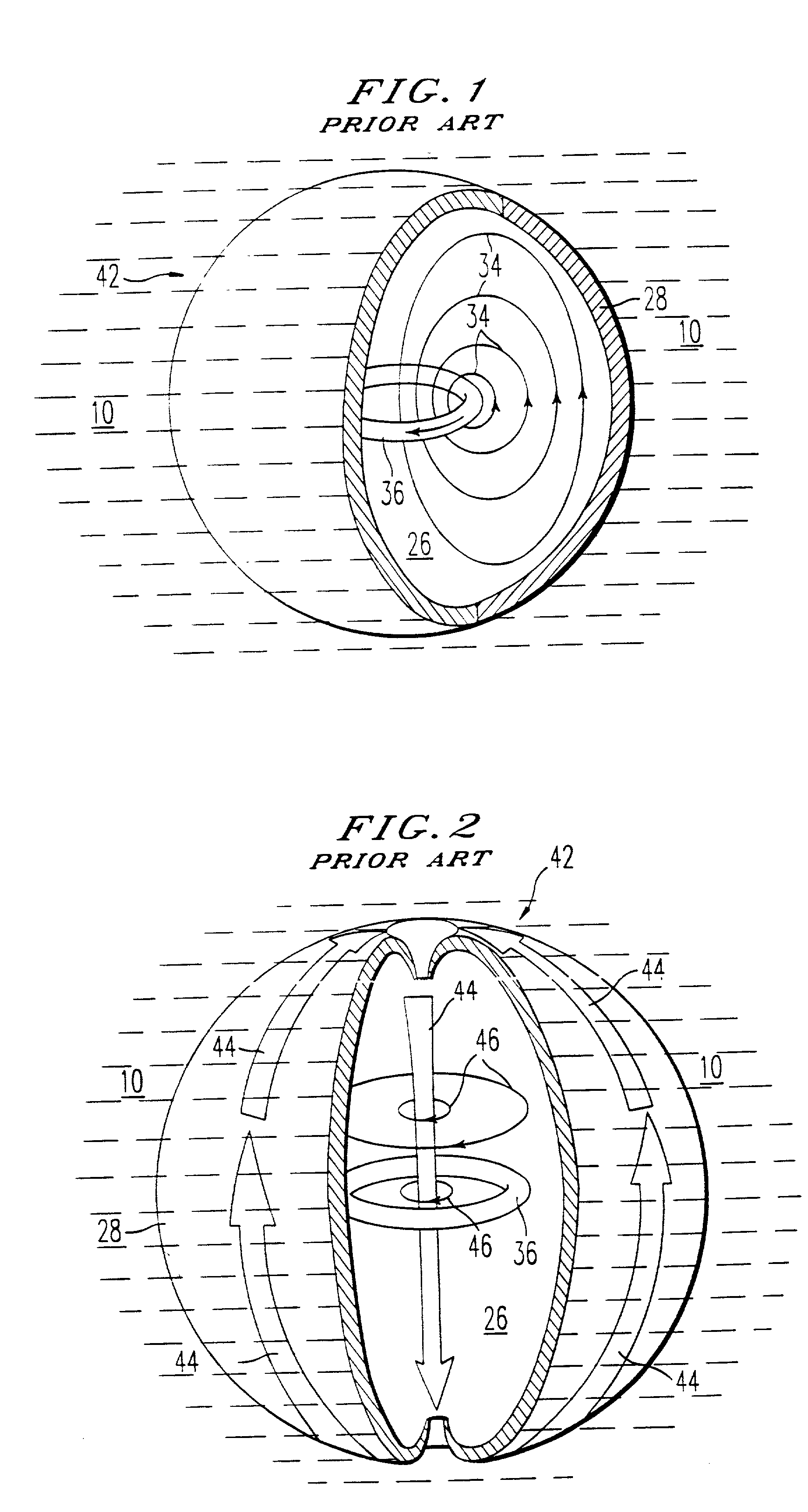
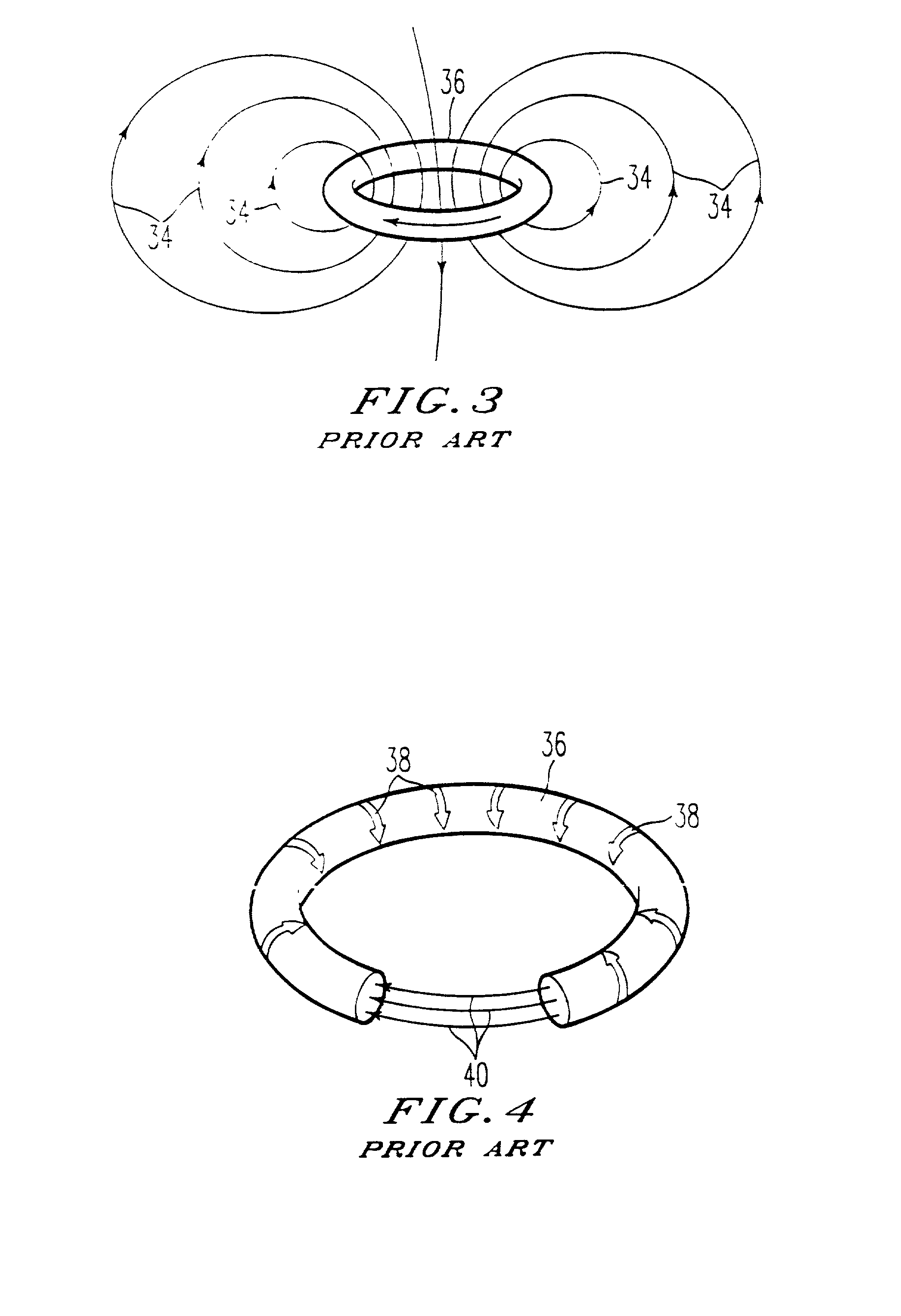
[0001] 1. Field of the Invention[0002] The present invention relates to a method and apparatus for forming a compound plasma configuration, as well as a new compound plasma configuration.[0003] 2. Discussion of the Background[0004] A compound plasma configuration, also known as a PMK (Plasma Mantle-Kernel) configuration has been described in U.S. Pat. Nos. 4,023,065; 4,891,180; 5,015,432; and 5,041,760. The structure of the PMK is shown in FIGS. 1 and 2 taken from U.S. Pat. No. 4,023,065. As described in that patent, the PMK 42 has three major regions: an inner kernel 36, a vacuum field region 26, and a mantle 28. Inner kernel 36 is a single toroidal current loop. The mantle 28 is composed of ionized material and is surrounded by a fluid 10, such as an atmosphere of gas. The vacuum field region 26, separates the mantle and the kernel.[0005] FIGS. 3 and 4 also taken from U.S. Pat. No. 4,023,065, provide more detail of the inner kernel. The plasma kernel 36 produces a poloidal magneti...

Claims


Application Information

Patent Timeline
IPC IPC(8): H05H1/02H05H1/04G21B1/11H05H1/24H05H1/54
CPCH05H1/04H05H1/52H05H1/54Y02E30/10
Inventor KOLOC, PAUL M.
Owner KOLOC PAUL M
Learn More