High frequency component, communication apparatus, and method for measuring characteristics of high frequency component

a technology of high frequency components and components, applied in the direction of measurement leads/probes, frequency to phase shift conversion, instruments, etc., can solve the problems of insufficient increase of the ratio of non-defective products to defective products, inability to accurately predict the change of characteristics, etc., and achieve the effect of easy measurement of characteristics

Inactive Publication Date: 2001-12-13
MURATA MFG CO LTD
View PDF5 Cites 129 Cited by
  • Summary
  • Abstract
  • Description
  • Claims
  • Application Information

AI Technical Summary

Benefits of technology

[0009] To overcome the above-described problems with the prior art, preferred embodiments of the present invention provide a method for easily measuring the characteristics of a high frequency circuit, which cannot be measured by an outwardly led-out terminal electrode, at the final product stage. Additionally, another preferred embodiment of the present invention provides a communication apparatus incorporating a high frequency component having desired characteristics.
[0012] In addition, in the high frequency component of preferred embodiments of the present invention, the diameter or width of the hole is preferably greater than the diameter or width of the signal measuring electrode pad and equal to or less than a length corresponding to about 1 / 4 wavelength of a frequency used in the component. This arrangement sufficiently suppresses the radiation or incidence of an electromagnetic wave of the used frequency band or a higher frequency band through the hole provided in the metal cover. As a result, the shielding effect of the metal cover is maintained.

Problems solved by technology

However, it is impossible to accurately predict how the characteristics change before and after covering with the metal cover.
Thus, the ratio of non-defective products to defective products cannot be sufficiently increased.

Method used


Image

  • High frequency component, communication apparatus, and method for measuring characteristics of high frequency component
  • High frequency component, communication apparatus, and method for measuring characteristics of high frequency component
  • High frequency component, communication apparatus, and method for measuring characteristics of high frequency component

Examples


Embodiment Construction

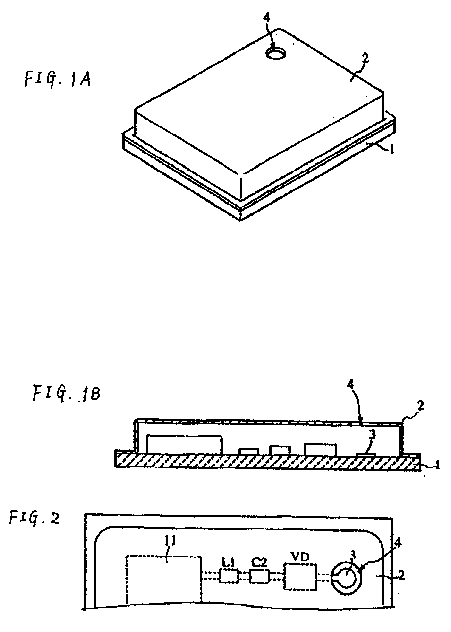
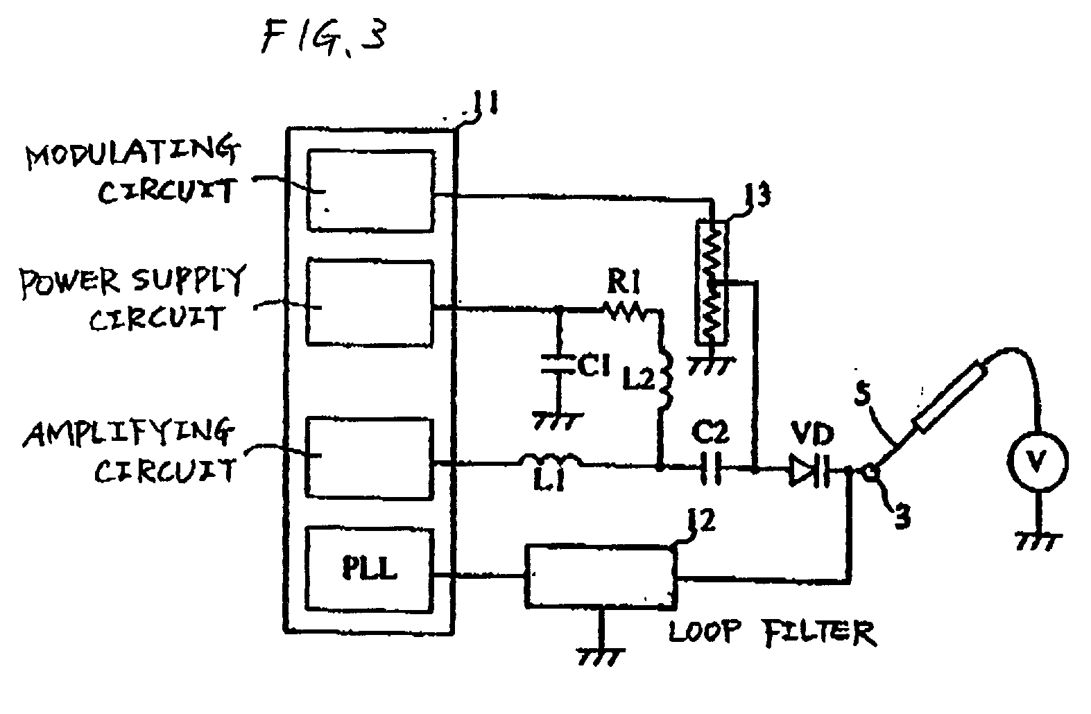
[0022] FIGS. 1A and 1B to FIG. 3 illustrate the structure of a PLL module as a high frequency component according to a first preferred embodiment of present invention.

[0023] FIG. 1A is a perspective view of the PLL module, and FIG. 1B is a sectional view thereof. In the PLL module, an electrode pattern is provided on an upper surface of a ceramic substrate 1, and a plurality of chip components are mounted thereon. In a portion of a metal cover 2, a hole 4 is provided in the vicinity of a signal measuring electrode pad 3.

[0024] FIG. 2 is a partial top view of the PLL module. The inner diameter of the hole 4 is greater than the diameter of the electrode pad 3 and is preferably substantially equal to or less than a length corresponding to about 1 / 4 wavelength of a frequency used in the component. For example, when the diameter of the electrode pad 3 is about 5 mm and the used frequency is 2.4 GHz, the diameter of the hole 4 is less than a length of about 31 mm corresponding to the abou...


PUM


Abstract

A high frequency component is constructed such that the characteristics of a high frequency circuit that cannot be measured only by an outwardly extending terminal electrode are easily measured at the final-product stage. In the high frequency component, a substrate has an electrode pattern provided including a signal measuring electrode pad. Additionally, chip components are mounted on the substrate. A metal cover has a hole provided near the signal measuring electrode pad. Through the hole, a probe of a measuring apparatus is inserted from the outside to abut with the electrode pad. With the arrangement, a voltage signal obtained at a predetermined point of the high frequency circuit is measured.

Description

BACKGROUND OF THE INVENTION[0001] 1. Field of the Invention[0002] The present invention relates to high frequency components having metal covers, communication apparatuses incorporating the high frequency components, and methods for measuring the characteristics of the high frequency components.[0003] 2. Description of the Related Art[0004] In a conventional high frequency component such as a voltage-controlled oscillator or a PLL module used in a mobile phone or other suitable device, various types of chip components are mounted on a substrate having an electrode pattern provided thereon. Additionally, a metal cover is attached over the substrate to cover the chip components provided on the substrate.[0005] Each of FIGS. 6A and 6B shows a conventional high frequency component. FIG. 6A is a perspective view of the high frequency component, and FIG. 6B is a sectional view thereof. In both figures, the reference numeral 1 denotes a ceramic substrate. On an upper surface of the substra...

Claims


Application Information

Patent Timeline
Patent Type & Authority Applications(United States)
IPC IPC(8): G01R1/06G01R31/00G01R31/28H03B1/00H05K9/00
CPCG01R31/2818G01R31/2822G01R31/2824
Inventor YOSHIDA, NORIOWATANABE, TAKAHIROITO, TOMONORI
Owner MURATA MFG CO LTD
Why Eureka
Try Eureka