Electronic power device

a technology of electric power device and power component, which is applied in the direction of power cables, cables, lighting and heating apparatus, etc., can solve the problems of increasing manufacturing cost and increasing the size of power components

Inactive Publication Date: 2001-12-27
ALSTOM TRANSPORT TECH SAS
View PDF0 Cites 51 Cited by
  • Summary
  • Abstract
  • Description
  • Claims
  • Application Information

AI Technical Summary

Benefits of technology

0004] The object of the present invention is to propose an electronic power c

Problems solved by technology

Nevertheless, such an electronic power device suffers from the drawback of generating parasitic switch loops of high inductance and thus of generating high voltage surges on switching, thus requiring the power components to be o

Method used


Image

  • Electronic power device
  • Electronic power device
  • Electronic power device

Examples


Embodiment Construction

[0021] To make the drawings easier to read, only those elements which are necessary for understanding invention have been shown.

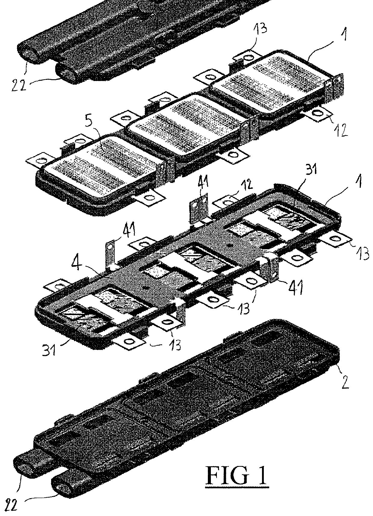
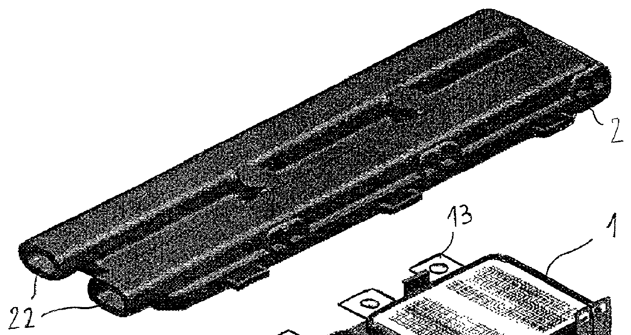
[0022] FIG. 1 it shows an electronic power device for a converter comprising two frames 1 of generally rectangular shape capable of being placed one against the other via one of their faces and capable of receiving respective cooling boxes 2 via their other faces. The frames 1 are substantially identical and they are made of an electrically insulating moldable material, e.g. an injection moldable resin of the polyphenylene dioxide type (PPO).

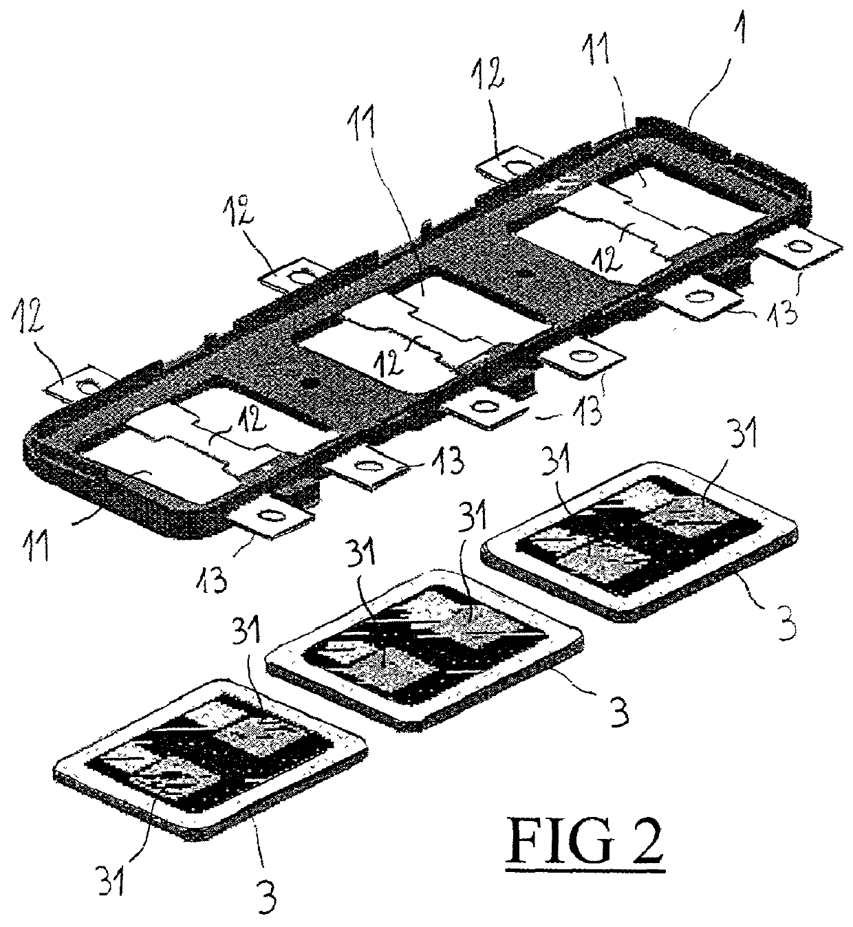
[0023] As shown in FIG. 2, each frame one has three openings 11 each receiving a support plate 3 of metallized aluminum nitride having two power components 31 brazed thereto, e.g. of the insulated gate bipolar transistor type (IGBT). The support plates 3 also have respective strips of copper 5 brazed to their faces opposite their faces receiving the IGBT components 31, these copper strips 5 having folds constituting mic...


PUM


Abstract

An electronic power device comprising support plates each having one face receiving one or more power components and an opposite face in contact with a cooling fluid for cooling said power components by conduction, wherein at least one support plate is associated with another support plate disposed facing it and provided with similar power components, and wherein the power components of the two facing support plates are disposed facing one another and in the immediate vicinity of one another.

Description

[0001] The invention relates to an electronic power device, and more particularly to a device comprising power chips fixed on support plates, the plates being cooled by a cooling fluid. The electronic power device of invention is particularly applicable to electronic devices used in converter type circuits for distributing power in railway applications, in which the delivered current and voltage values are particularly large.[0002] In conventional manner, it is known to cool an electronic power component by coupling it to a heat exchanger and by inserting a ceramic plate between these two components to isolate the heat exchanger electrically from the component. Thus, document FR 2 775 416 discloses an electronic power device having power chips fixed on one face of a support plate, the other face of the plate having a heat exchanger. It is also known from that document to associate support plates in pairs by placing them on opposite sides of a cooling circuit, the heat exchangers the...

Claims


Application Information

Patent Timeline
IPC IPC(8): H01L23/473H01L25/07H01L25/18H02M7/00
CPCH02M7/003H01L2924/0002H01L2924/00H05K7/2089
Inventor CETTOUR-ROSE, JACQUESFELLMANN, DANIELPETITBON, ALAIN
Owner ALSTOM TRANSPORT TECH SAS
Why Eureka
Try Eureka