Signaling system for drilling

a technology of signaling system and drilling bit, which is applied in the direction of survey, core removal, reradiation, etc., can solve the problems of significant pulse reflection at discontinuities in process pipework, damage or erode drilling equipment, and unsatisfactory pulses

Inactive Publication Date: 2002-01-24
GEOLINK UK
View PDF0 Cites 20 Cited by
  • Summary
  • Abstract
  • Description
  • Claims
  • Application Information

AI Technical Summary

Benefits of technology

[0017] an actuator coupled with the valve element and operative to move the valve element between a closed position in which it prevents discharge of pressure fluid from the control passage, and an open position in which it allows the pressure fluid to flow through the control passage;
[0019] a resiliently yieldable arrangement acting between the actuator and the valve element in order to define a yieldable limit to the pressure of the fluid in the control passage and thereby control the pressure pulse generated by the movement of the control element to the closed position.
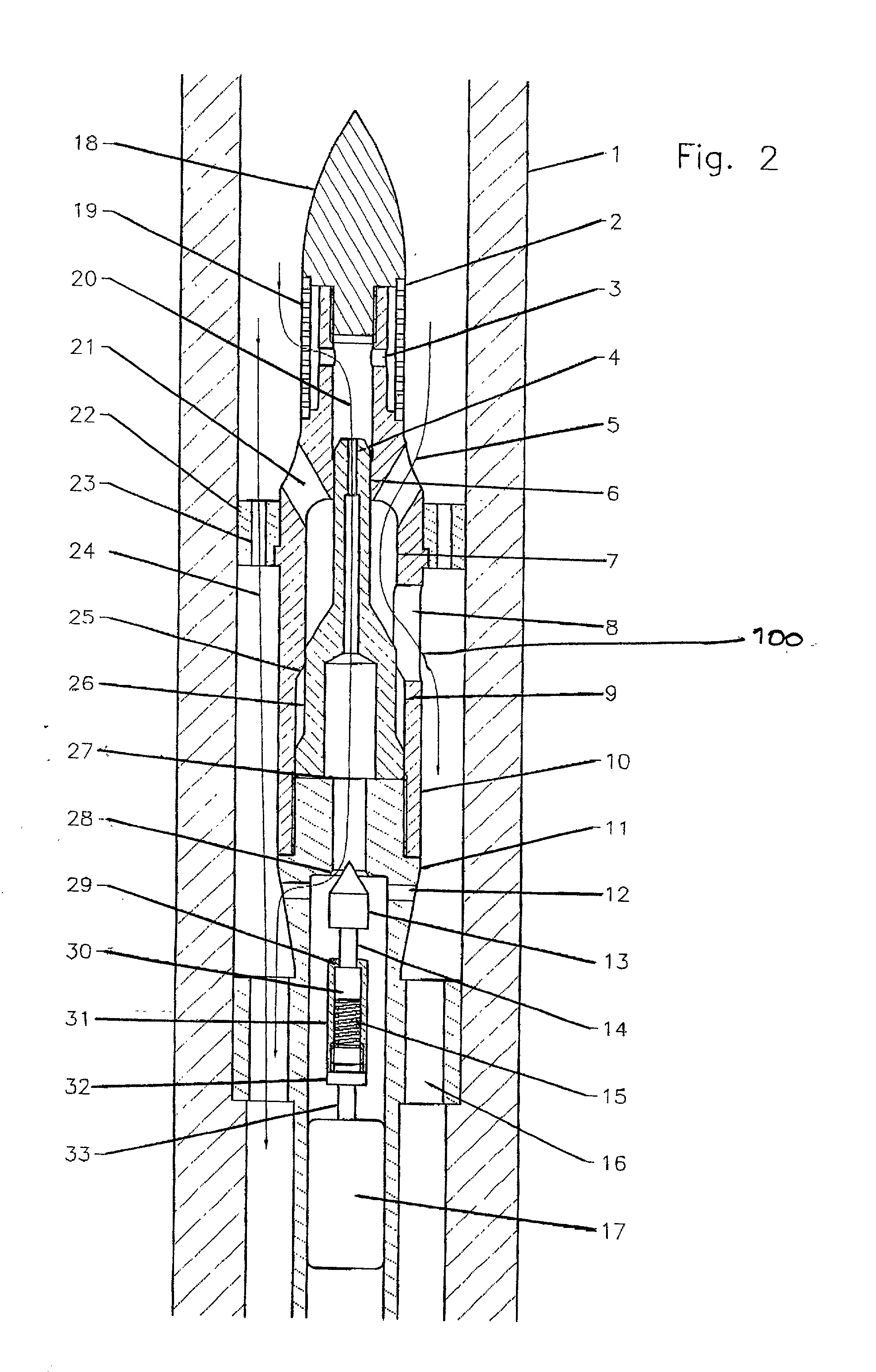
[0022] FIG. 4 is a view, similar to FIGS. 2 and 3, but showing the internal components in a partly closed position, whereby to reduce, when necessary, the magnitude of the pressure of the signaling pulse generated.

Problems solved by technology

It is a disadvantage of this type of pulse generator that the magnitude of the transient pressure change which occurs downhole is highly dependent on the flowrate of the drilling fluid.
Although in any given drilling situation a certain minimum pulse amplitude is needed so that the pulse will be detectable at the earth's surface, it is unsatisfactory for the pulse to be made too large: the imposition of a succession of severe flow restrictions can stress, damage or erode the drilling equipment and starve the drilling bit of fluid.
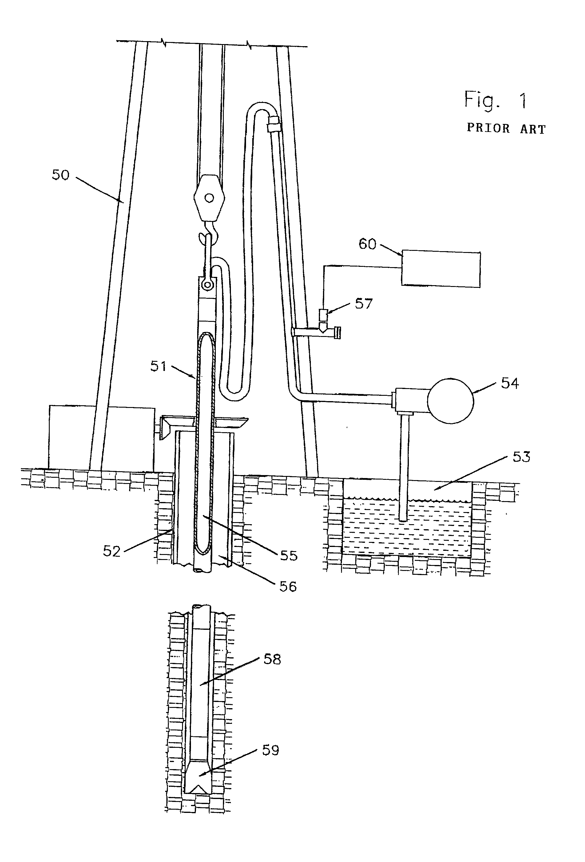
Furthermore, when mud pressure pulses are too large, significant pulse reflections occur at discontinuities in the process pipework.
This typically involves replacing parts of the downhole system, and is time consuming and expensive.

Method used


Image

  • Signaling system for drilling
  • Signaling system for drilling
  • Signaling system for drilling

Examples


Embodiment Construction

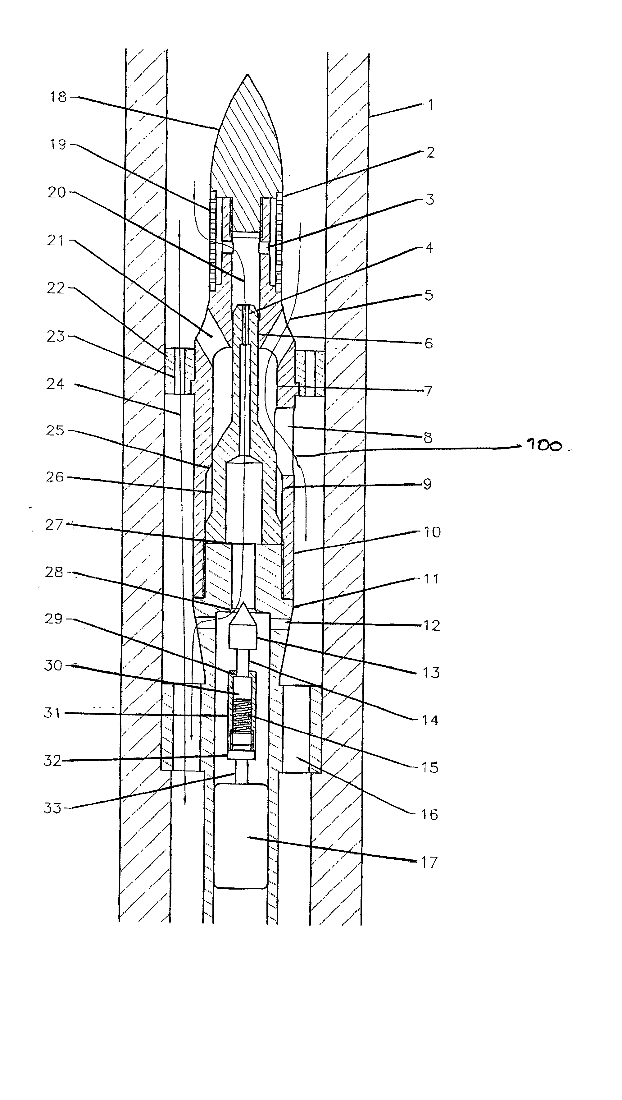
[0023] FIG. 2 shows a mud pulse generator, designated generally by reference 100, and mounted in a drill collar (1). The pulse generator is generally of the type described in U.S. Pat. No. 3,958,217, in which the energy needed to operate the restricting valve is derived from the drilling fluid. Drilling fluid flows down through the space and passages in the bore of drill collar (1), on through a drilling motor (if fitted) and thence to the drill bit (not shown). The drilling fluid returns upwards in the annular space between the outside of the drill collar (1) and the rock formation being penetrated (not shown). In a typical installation the fluid is "drilling mud". However, other fluids may be used, including gas, foam or mist.

[0024] A housing is positioned in the path of the pressurised drilling fluid and comprises a body (10), located inside the drill collar (1) and having three different internal bores (6), (7) and (9).

[0025] A control element in the form of piston (26) is a sli...


PUM


Abstract

A pressure pulse generator for use in transmitting pressure signals to surface in a fluid-based drilling system. The generator is arranged in use in the path of a pressurized fluid to operate a drilling assembly and is capable of being actuated to generate pressure signals in such fluid for transmission to surface pressure monitoring equipment. The pulse generator includes pulse height compensation to keep the pulse height within acceptable limits over a wide flow range.

Description

[0001] This invention relates to a system of communication employed during the drilling of boreholes in the earth for purposes such as oil or gas exploration and production, the preparation of subterranean services ducts, and in other civil engineering applications.BACKGROUND TO INVENTION[0002] Taking the drilling of oil and gas wells as an example, it is highly desirable both for economic and for engineering reasons, to obtain information about the progress of the borehole and the strata which the drilling bit is penetrating from instruments positioned near the drilling bit, and to transmit such information back to the surface of the earth without interruption to the drilling of the borehole. The generic name associated with such techniques is "Measurement-while-Drilling" (MWD). Substantial developments have taken place in MWD technology during the last twenty-five years.[0003] One of the principal problems in MWD technology is that of reliably telemetering data from the bottom of ...

Claims


Application Information

Patent Timeline
Patent Type & Authority Applications(United States)
IPC IPC(8): E21B47/18
CPCE21B47/187E21B47/24
Inventor INNES, FRANK
Owner GEOLINK UK
Why Eureka
Try Eureka