Method and computer program product for estimating wire loads and method and computer program product for inserting repeater cells

a repeater cell and wire load technology, applied in the field of method and computer program product for estimating wire load and method and computer program product for inserting repeater cells, can solve the problems of increasing originating from gate delay, and originating from wiring delay, so as to reduce the delay time of signal transmission

Inactive Publication Date: 2002-01-24
KK TOSHIBA
View PDF3 Cites 40 Cited by
  • Summary
  • Abstract
  • Description
  • Claims
  • Application Information

AI Technical Summary

Problems solved by technology

Along with the advent of the miniaturization of LSIs, the signal delay originating from wiring delays, rather than originating fr...

Method used


Image

  • Method and computer program product for estimating wire loads and method and computer program product for inserting repeater cells
  • Method and computer program product for estimating wire loads and method and computer program product for inserting repeater cells
  • Method and computer program product for estimating wire loads and method and computer program product for inserting repeater cells

Examples


first embodiment

[0057] As illustrated in FIG. 3, the wire load estimating system in accordance with the present invention is composed at least of a netlist reading unit 14, a location information reading unit 20, a cell library reading unit 26, a connection point coordinate calculation unit 30, a global routing unit 34, a wire load estimating unit 38 and an output unit 42.

[0058] The netlist reading unit 14 serves to read the netlist 10 in order to generate connection information 12 including at least the names of signals, the identification names of instances and the names of terminals, which are described in the netlist.

[0059] The "instances" includes cells, macro blocks and synthesized blocks. A cell is a unit consisting of a relatively simple circuit, with which a LSI circuit is designed A macro block is a relatively complicated cell such as a memory, an ALU, a multiplexer or the like. The synthesized block is composed of a combination of several cells.

[0060] The location information reading uni...

second embodiment

[0141] [THE SECOND EMBODIMENT]

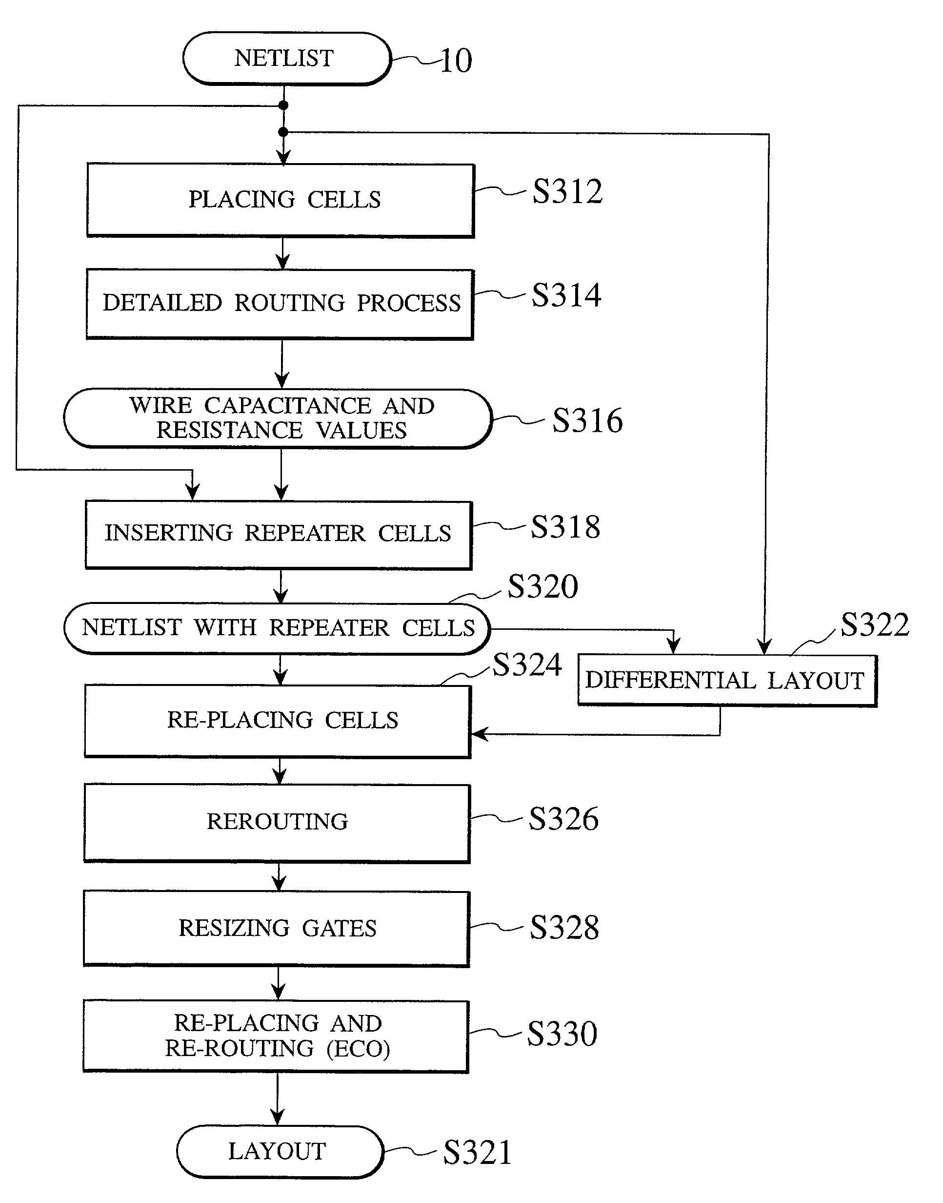
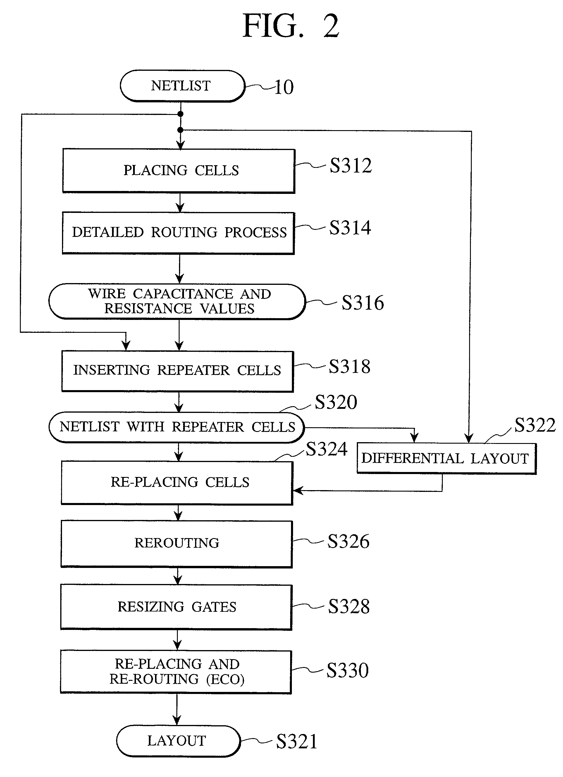
[0142] As illustrated in FIG. 20, the method of inserting a repeater cell in accordance with the second embodiment comprises a global routing step S452 of routing signals exchanged between regions (global signals) on the basis of the netlist 10 and global floor plan data 450, a calculation step S454 of calculating the wire capacitance values and the wire resistance values of the global routing on the basis of the result of the global routing process, a temporary repeater cell inserting step S458 of temporarily inserting a repeater cell(s) and outputting the netlist 460 with a temporary repeater cell(s) after reading the netlist 10 and the wire capacitance values and the wire resistance values 456, a cell placing step S462 of outputting the cell coordinates by the use of the netlist 460 with a temporary repeater cell(s).

[0143] Also, as illustrated in FIG. 20, the method of inserting a repeater cell in accordance with the second embodiment comprises an id...


PUM


Abstract

A wire load estimating method comprises (1) reading a netlist; (2) generating connection information including the names of signals, the identification names and the names of pins of instances which include cells, macro blocks and synthesized blocks as described in the netlist; (3) dividing an area of a chip into two or more regions and determining connection point coordinates for each of the regions by the use of the connection information and locations of the instances as placed; (4) determining a wiring path by the use of the connection point coordinates; and (5) estimating a wire capacitance value and a wire resistance value with reference to the wiring path.

Description

[0001] This application is based upon and claims the benefit of priority from the prior Japanese Patent Application Nos. 11-371859, filed Dec. 27, 1999 and 2000-196811, filed Jun. 29, 2000; the entire contents of which are incorporated herein by reference.[0002] 1. Field of the Invention[0003] The present invention is related to a wire load estimating method and a wire load estimating computer program product for estimating wire loads between instances such as cells, macro blocks and synthesized blocks and a repeater cell inserting method and a repeater cell inserting computer program product for determining the location of a repeater cell to be inserted on a long wire.[0004] 2. Description of the Related Art[0005] Along with the advent of the miniaturization of LSIs, the signal delay originating from wiring delays, rather than originating from gate delays, become a serious problem. Because of this, it is significantly important to estimate wire loads (the wire resistance and the wi...

Claims


Application Information

Patent Timeline
IPC IPC(8): G06F17/50
CPCG06F17/5036G06F17/5068G06F30/367G06F30/39
Inventor OTAGURO, YUKIO
Owner KK TOSHIBA
Why Eureka
Try Eureka