Structure of installing wire harness for sliding door

a wire harness and sliding door technology, applied in the direction of cables, cable arrangements between relatively moving parts, roofs, etc., can solve the problems of poor flexibility of electric wires, difficulty in application, and damage to wires 119

Inactive Publication Date: 2002-02-07
YAZAKI CORP
View PDF0 Cites 28 Cited by
  • Summary
  • Abstract
  • Description
  • Claims
  • Application Information

AI Technical Summary

Problems solved by technology

However, there has been an anxiety in the above described structure that the wire 119 may be damaged because the wire 119 has to be rolled up many times on the reel 120.
There has been a further problem that application has been difficult, since the wire harness including a number of circuits (electric wires) has poor flexibility.
However, this structure has had a problem that because the flat cable is composed of printed circuit conductors and insulating sheets having small sectional areas, its power supply capacity is too small and can be only used to supply of electric current having small capacity or signals, but cannot be used for power supply.
There has been a further problem that in case where a small number of electric wires are connected to various functional components by a junction switch system, this would result in an increase of cost.
Therefore, there has been an anxiety that the wire harness may be caught between the sliding door and the vehicle body.
On this occasion, the wire harness tends to hang lower than the step, and it has been feared that the wire harness may be caught between the step and a door trim of synthetic resin inside the sliding door.
If the wire harness should happen to be caught, the protective tube covering the wire harness may be damaged or the electric wires composing the wire harness may be broken in the worst case.
In this case, however, strong pressure is exerted to the wire harness and the protective tube even in a fully open state or a fully closed state of the sliding door in which the leaf spring is not required, and the protective tube is likely to be damaged.
In addition, the cost for the leaf spring will be increased.
In case where the wire harness is arranged diagonally upwardly from the sliding door to the vehicle body, it has been feared that the wire harness may be bent at an angle as large as 90 degree, exerting superfluous stress to the bent portion.
In this case too, the wire harness may be damaged, or expanding and contracting movement of the wire harness following the opening and closing operation of the sliding door may not be smoothly conducted.
Further, because the corrugated tube has a relatively large diameter and requires a large space for arrangement, there has been problems with respect to space and design that the harness slack absorbing apparatus may become large-sized, and the door trim must be bulged into the vehicle room.

Method used


Image

  • Structure of installing wire harness for sliding door
  • Structure of installing wire harness for sliding door
  • Structure of installing wire harness for sliding door

Examples


Embodiment Construction

[0040] Now, an embodiment according to the present invention will be described referring to the drawings.

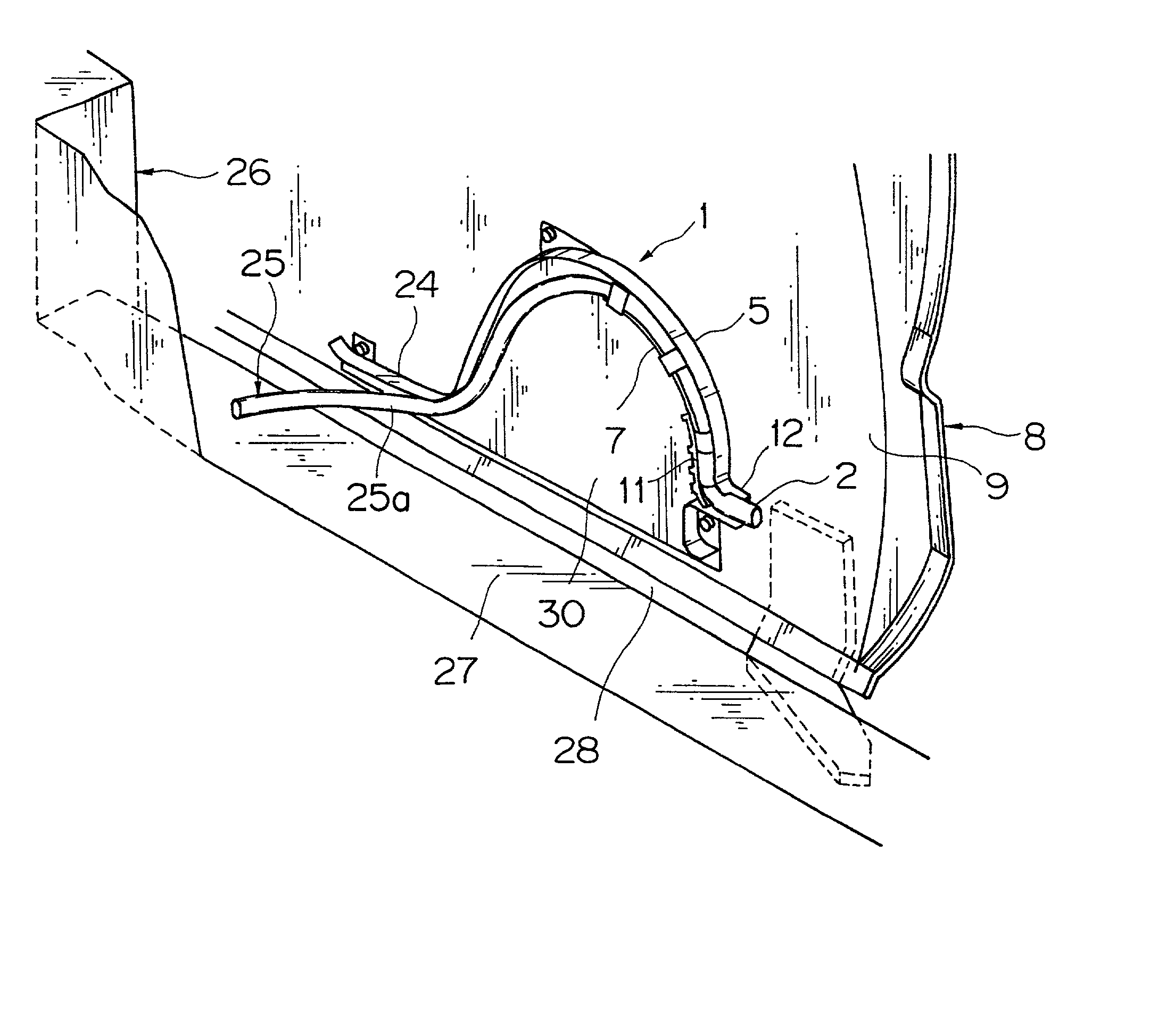
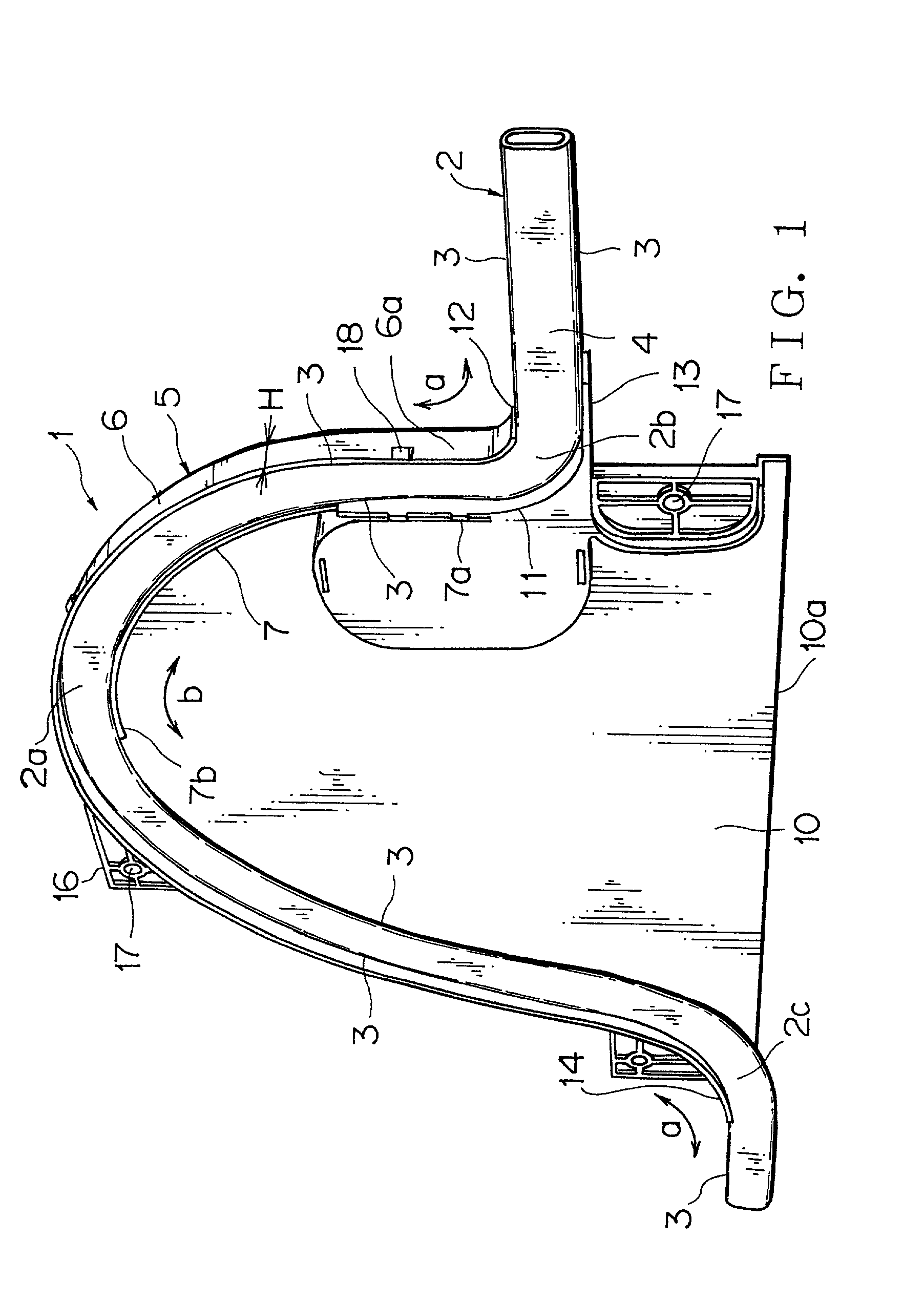
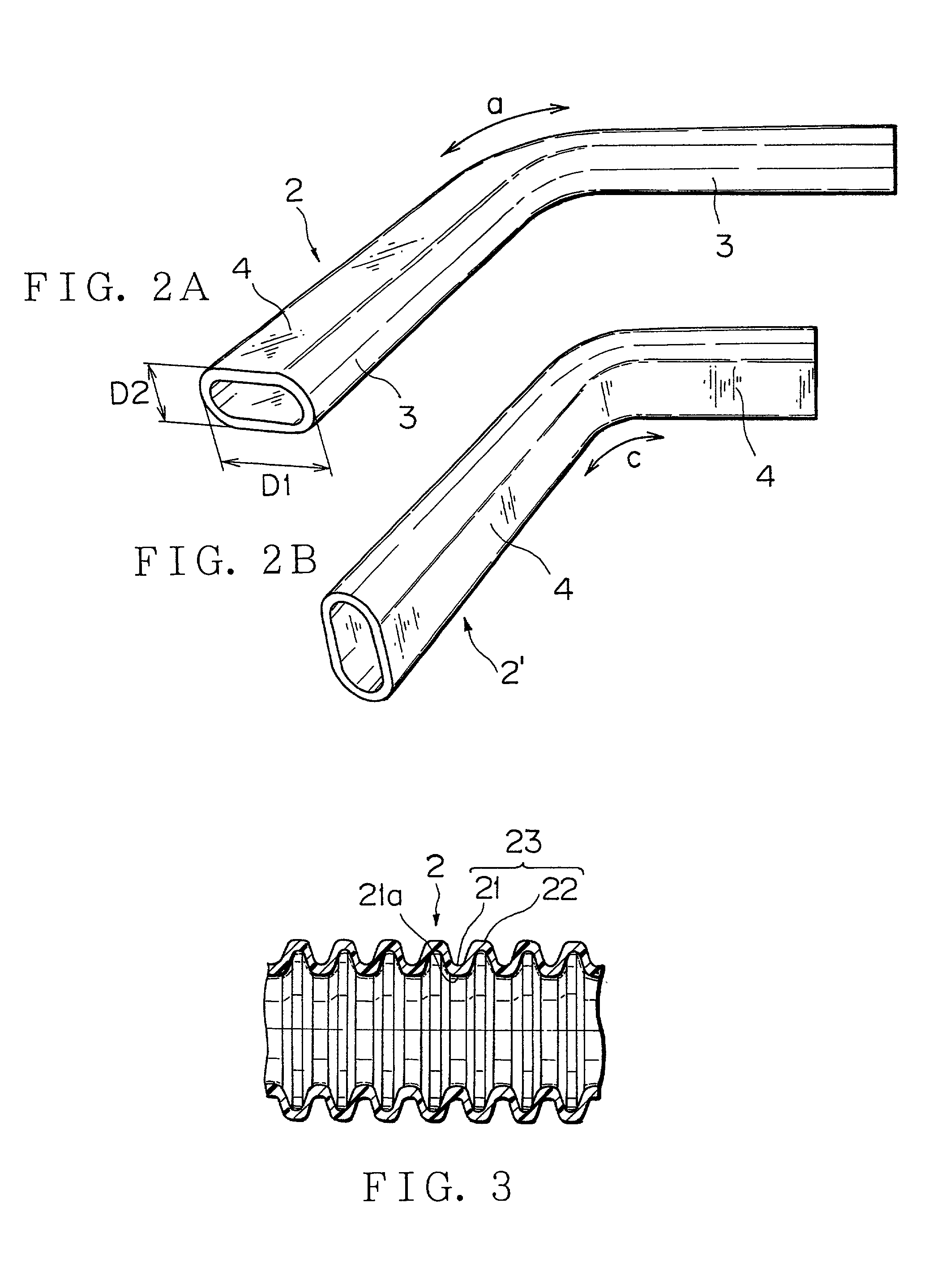
[0041] There is provided an apparatus 1 for absorbing slack (extra length) of a wire harness at a sliding door side employing a flat corrugated tube 2 having an oval shape in cross section as a harness protective tube in which electric wires are contained. The flat corrugated tube 2 is curved in a direction of its longer diameter portions 3 (for example, in a direction where the longer diameter portions 3 on an upper side approach each other as shown by an arrow a in FIG. 1 and the longer diameter portions 3 on a lower side approach each other as shown by an arrow b in FIG. 1), so that the longer diameter portions 3 are positioned in a vertical direction, and its shorter diameter portions 4 are positioned in a horizontal direction.

[0042] Referring to FIG. 1, the harness slack absorbing device 1 consists of a protector 5 made of synthetic resin and having a curved part 6 in a semi...


PUM

PropertyMeasurementUnit
angleaaaaaaaaaa
structureaaaaaaaaaa
diameteraaaaaaaaaa

Abstract

A structure of installing a wire harness for a sliding door includes a harness protective tube 2 in which electric wires are contained to compose the wire harness. The harness protective tube 2 is curved at the sliding door side and installed at a vehicle body side. The harness protective tube 2 has an oval shape in cross section, and is curved in a direction of its longer diameter portions 3 at the sliding door side so that the longer diameter portions are positioned in a vertical direction, whereby harness slack absorbing function is imparted to the harness protective tube. The longer diameter portions 3 are supported by a support part 11 at the sliding door side, and the harness protective tube 2 is curved in a direction of the longer diameter portions extending from the support part to the vehicle body side. There is provided a protector 5 in which the support part 11 is positioned, and the harness protective tube 2 is contained in a curved state in a direction of the longer diameter portions 3. The longer diameter portions 3 in a curved section 2a of the harness protective tube 2 are urged upward by an elastic member 7.

Description

[0001] 1. Field of the Invention[0002] The present invention relates to a structure of installing a wire harness for a sliding door, and more particularly to the structure of installation in which the wire harness is installed from a sliding door side toward a vehicle body side employing a harness protective tube such as a corrugated tube in an oval shape so that slack of the wire harness following opening and closing movement of the sliding door can be absorbed.[0003] 2. Description of the Related Art[0004] There have been proposed various kinds of structures of installing wire harnesses for sliding doors in order to supply electric power from a vehicle body (power supply) to functional components in the-sliding doors which are employed in a one boxed car or a station wagon, or to send electric signals from the sliding door to the vehicle body.[0005] The sliding door is equipped with various functional components such as a power window motor, door lock unit, speaker, switch unit, e...

Claims


Application Information

Patent Timeline
Patent Type & Authority Applications(United States)
IPC IPC(8): B60J5/06B60R16/02H01B7/00H02G3/04H02G3/38H02G11/00
CPCB60R16/0215H02G3/0468H02G11/006
Inventor AOKI, TOHRUDOSHITA, KENICHITSUNODA, MITSUNORIFUKUMOTO, RHOICHI
Owner YAZAKI CORP
Why Eureka
Try Eureka