Honeycomb filter and manufacturing method of the same

a technology of honeycomb and manufacturing method, which is applied in the field of honeycomb filters, can solve the problems of increasing the pressure loss in the initial state of the obtained honeycomb structure, increasing the pressure loss of the honeycomb structure, and increasing the pressure loss when a pm is deposited, so as to suppress the increase of an initial pressure loss and suppress the rise of a pressure loss. , the effect of high open area ratio

Active Publication Date: 2012-09-27
NGK INSULATORS LTD
View PDF2 Cites 19 Cited by
  • Summary
  • Abstract
  • Description
  • Claims
  • Application Information

AI Technical Summary

Benefits of technology

[0034]In a honeycomb filter of the present invention, a porous collecting layer is disposed on the surface of a partition wall parent material in at least remaining cells. Moreover, the collecting layer has a constitution in which a plurality of particles combine or intertwine with one another. Furthermore, the collecting layer includes flat plate-like particles as the plurality of particles. The plurality of particles are particles in which an average long diameter is 0.2 μm or larger and smaller than 10 μm, an average value of ratios (long diameters / short diameters) of the long diameters to the short diameters of the respective particles is smaller than 3, and an average value of ratios (the long diameters / thicknesses) of the long diameters to the thicknesses of the respective particles is 3 or larger, and an open area ratio of the surface of the collecting layer is 10% or larger. Therefore, it is possible to suppress the increase of an initial pressure loss of the honeycomb filter, and it is also possible to suppress the rise of a pressure loss when a particulate matter is deposited. In particular, the collecting layer of the honeycomb filter of the present invention has a constitution in which the above plurality of particles combine or intertwine with one another in a state where the particles are not excessively aligned along the surface of the partition wall parent material. In consequence, the above high open area ratio is realized.
[0035]Moreover, a manufacturing method of a honeycomb filter according to the present invention “comprises a collecting layer forming step of sucking powder including flat plate-like particles together with air through inflow-side end surfaces of remaining cells of a plugged honeycomb structure, and attaching the powder to the surface of the partition wall parent material in the remaining cells, wherein as the powder, there is used powder including particles having an average long diameter of 0.2 μm or larger and smaller than 10 μm, an average value of ratios (the long diameters / short diameters) of the long diameters to the short diameters of the respective particles which is smaller than 3, and an average value of ratios (the long diameters / thicknesses) of the long diameters to the thicknesses of the respective particles which is 3 or larger, and in the used powder, a percentage of non plate-like particles having the long diameters which are smaller than a length of ⅕ of the average long diameter, and having the long diameters / the thicknesses smaller than 2 in the number of all the particles constituting the powder is smaller than 10%”. In consequence, the collecting layer can be formed of the plate-like particles sucked together with the air so that the plate-like particles are not excessively aligned with one another or the particles are not excessively aligned on the surface of the partition wall parent material. Therefore, it is possible to easily manufacture a honeycomb filter in which it is possible to lower an initial pressure loss and to suppress the rise of a pressure loss when a particulate matter is deposited.

Problems solved by technology

However, when spherical particles are used as described above, particles penetrate into the pores of the partition walls (a partition wall parent material) of a honeycomb structure, and an initial pressure loss of the honeycomb structure becomes high.
This has caused a problem that the pressure loss in an initial state of the obtained honeycomb structure increases.
Moreover, such a honeycomb structure also has a problem that the rise of the pressure loss when a PM is deposited (especially, in a deposition initial stage where the PM starts to be deposited) becomes large.
This has been a problem that a pressure loss in an initial state of an obtained honeycomb structure increases.
Moreover, such a honeycomb structure also has a problem that the rise of a pressure loss when a PM is deposited (especially, in a deposition initial stage where the PM starts to be deposited) becomes large.

Method used


Image

  • Honeycomb filter and manufacturing method of the same
  • Honeycomb filter and manufacturing method of the same
  • Honeycomb filter and manufacturing method of the same

Examples


example 1

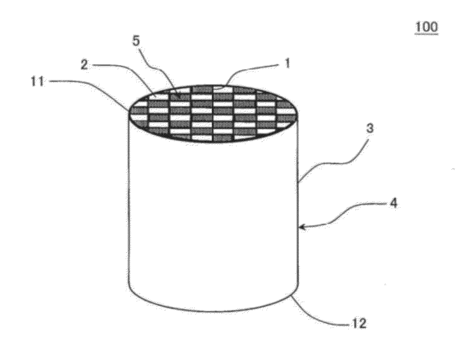
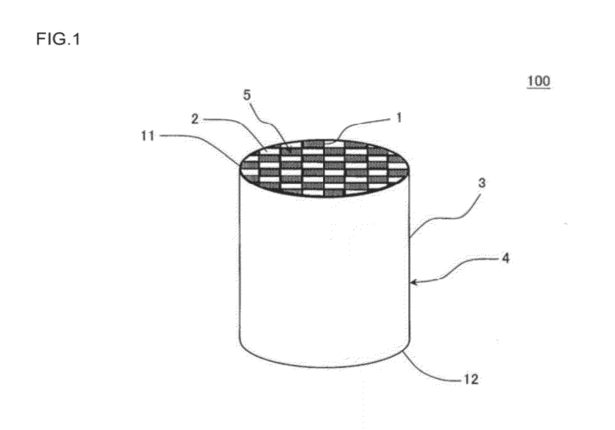
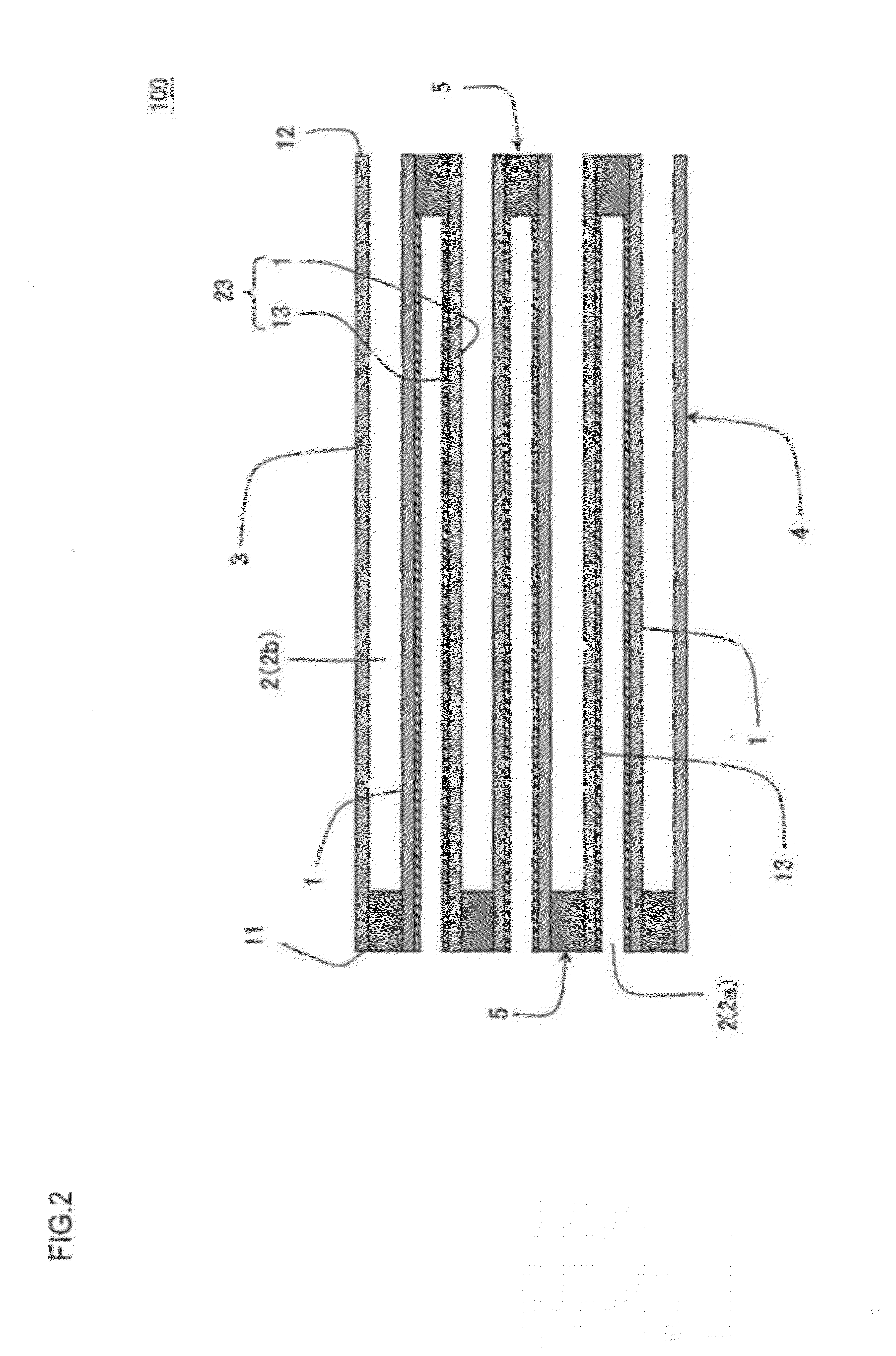
[0133]As a ceramic raw material, a cordierite forming raw material (talc, kaolin and alumina) was used. A mass ratio of talc, kaolin and alumina was a mass ratio at which cordierite was obtained after firing. In 100 parts by mass of the ceramic raw material, 4 parts by mass of binder (methylcellulose) and 35 parts by mass of water were mixed to obtain a ceramic forming raw material. The obtained ceramic forming raw material was kneaded by using a kneader, to obtain a kneaded material. The obtained kneaded material was extruded by using a vacuum extrusion-forming machine, to obtain a honeycomb formed body. In the obtained honeycomb formed body, a partition wall thickness was 304.8 μm, a cell density was 46.5 cells / cm2, and the whole shape was a cylindrical shape (a diameter of an end surface was 127 mm, and a length in a cell extending direction was 152.4 mm). As a cell shape, a shape orthogonal to the cell extending direction was a square. The obtained honeycomb formed body was drie...

examples 2 to 12

[0178]Plugged honeycomb structures were prepared in the same manner as in Example 1, and honeycomb filters were prepared in the same manner as in Example 1, except that raw materials (collecting layer raw material powder) to form collecting layers shown in Table 1 and Table 2 were used. It is to be noted that in Examples 4 and 10, talc powder was used as the collecting layer raw material powder. In Example 5, kaolin powder was used as the collecting layer raw material powder. In Example 12, alumina powder was used as the collecting layer raw material powder. In Examples 2, 3, 6 to 9 and 11, boehmite powder was used as the collecting layer raw material powder. The boehmite powder was fired to form a collecting layer made of alumina. Evaluations were performed in the same manner as in Example

1. The results are shown in Table 1 and Table 2.

TABLE 1Example 1Example 2Example 3Example 4Example 5Example 6Example 7Honeycomb base materialCordieriteCordieriteCordieriteCordieriteCordieriteCordi...

example 13

[0179]A honeycomb structure was prepared in the same manner as in Example 1 except that polymethyl methacrylate (PMMA) having an average particle diameter of 60 μm was further added to a ceramic forming raw material and that boehmite was used as collecting layer raw material powder. A content of PMMA in the ceramic forming raw material was 10 mass %. Evaluations were performed in the same manner as in Example 1. The results are shown in Table 2.


PUM

PropertyMeasurementUnit
diametersaaaaaaaaaa
diametersaaaaaaaaaa
porosityaaaaaaaaaa

Abstract

There is provided a honeycomb filter including: a honeycomb base material; plugged portions; and a porous collecting layer disposed on the surface of the partition wall parent material in at least the remaining cells. The collecting layer has a constitution in which a plurality of particles combine or intertwine with one another, and the collecting layer includes flat plate-like particles as the plurality of particles. The plurality of particles are particles in which an average long diameter is 0.2 μm or larger and smaller than 10 μm, an average value of ratios (long diameters/short diameters) of the long diameters to the short diameters of the respective particles is smaller than 3, and an average value of ratios (the long diameters/thicknesses) of the long diameters to thicknesses of the respective particles is 3 or larger. An open area ratio of the surface of the collecting layer is 10% or larger.

Description

BACKGROUND OF THE INVENTION[0001]1. Field of the Invention[0002]The present invention relates to a honeycomb filter, and a manufacturing method of the honeycomb filter. More particularly, it relates to a honeycomb filter which can suppress the increase of an initial pressure loss and also suppress the rise of a pressure loss when a particulate matter is deposited, and also relates to a manufacturing method of a honeycomb filter which can manufacture such a honeycomb filter.[0003]2. Description of Related Art[0004]In gases discharged from internal combustion engines such as diesel engines, various types of combustion apparatuses and the like, a large amount of particulate matter (PM) mainly composed of soot is included. When this PM is discharged as it is to the atmosphere, environmental pollutions are caused. Therefore, a diesel particulate filter (DPF) for collecting the PM is mounted on an exhaust system of an exhaust gas.[0005]As such a DPF, there has been used, for example, a ho...

Claims


Application Information

Patent Timeline
Patent Type & Authority Applications(United States)
IPC IPC(8): B01D46/00B05D3/02B05D7/22
CPCB01D46/2429B01D39/2006B01D2239/0478B01D39/2072B01D39/2093B01D39/2058B01D46/2474B01D46/24491B01D46/24492B01D46/2484B01D46/2482
Inventor ISODA, YOSHINORIKIKUCHI, YOSHIO
Owner NGK INSULATORS LTD
Why Eureka
Try Eureka