Graphics system configured to perform distortion correction

a distortion correction and graphics system technology, applied in image enhancement, pulse technique, instruments, etc., can solve the problems of increased brightness of overlap regions, difficult configuration, and high cos

Inactive Publication Date: 2002-02-07
ORACLE INT CORP
View PDF5 Cites 55 Cited by
  • Summary
  • Abstract
  • Description
  • Claims
  • Application Information

AI Technical Summary

Problems solved by technology

The increased brightness of the overlap region may be annoying to a viewer of the integrated image AFGD.
The overlap-brightness problem exists when any number of projected images are overlapped.
Although, video boxes provide some measure of correction to the overlap-brightness problem, they may be expensive and may not be easy to configure.
Furthermore, their functionality may be limited.
In reality, the intensity distribution of a projected image may be highly non-uniform for a number of different reasons.
However, many distortion mechanisms conspire to defeat this desired end.
For example, in a scenario where a projection device projects onto a screen which is not centered on or perpendicular to the projection axis, the resulting geometric distortion may amount to a significant fraction of the displayed pixel array.
Thus, images displayed in the left and right physical arrays may appear distorted.
Even if the distortion of each physical array is small, there may be relative distortions between the left and right physical arrays.
As another example, the distortions of the left and right physical arrays may arise from manufacturing imperfections in the light processing chips of each projection device.
However, if the overlap region is minimized, it becomes difficult to perform edge blending with the prior art video box technology.
Thus, there may appear an uneven line of brightness along the interface of the physical arrays.
However, real projection devices depart from this ideal behavior because of distortions inherent in the displays, the lenses, the alignment of the displays with res

Method used


Image

  • Graphics system configured to perform distortion correction
  • Graphics system configured to perform distortion correction
  • Graphics system configured to perform distortion correction

Examples


second embodiment

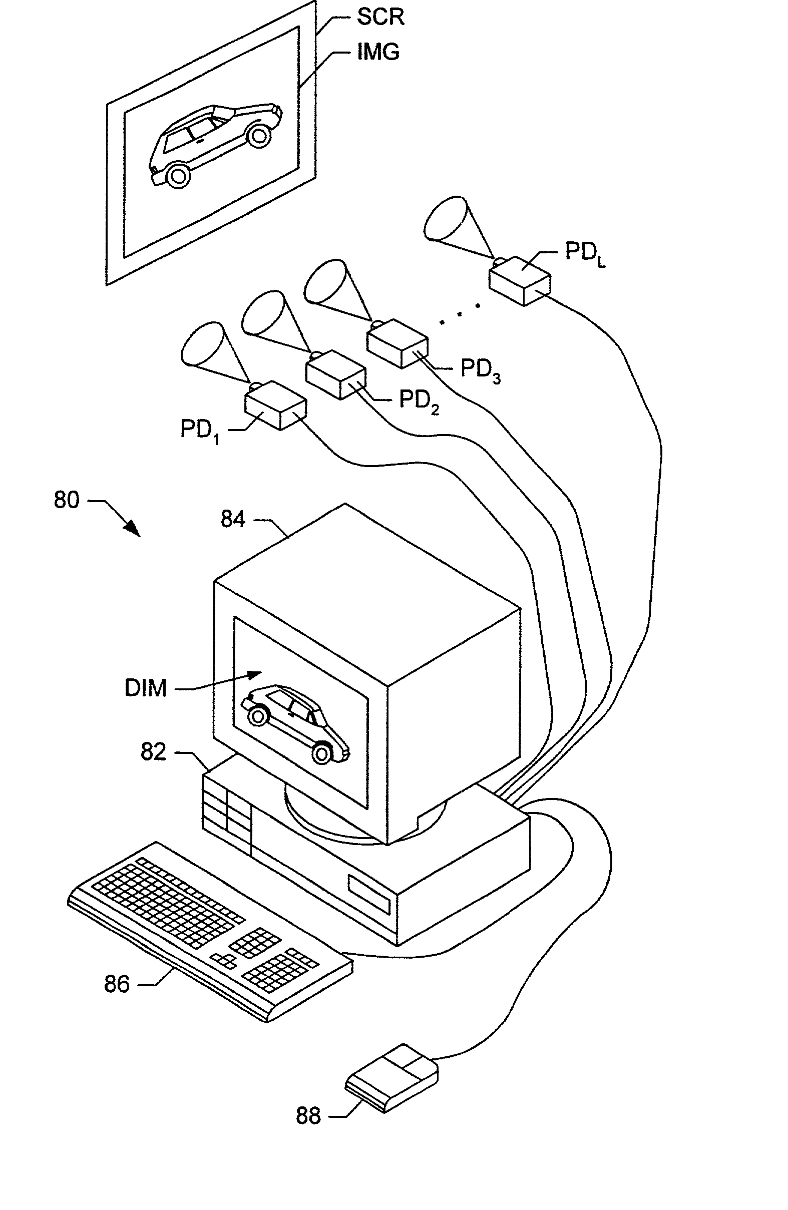
[0150] In a second embodiment, graphics system 112 comprises graphics boards 114-1 through 114-M which couple to projection devices PD.sub.1-PD.sub.L in a one-to-two fashion, i.e. generic graphics board 114-I couples to and generates video signals for two projection devices PD.sub.1 and PD.sub.I+1 as shown in FIG. 8C. Thus, integer M equals L / 2.

third embodiment

[0151] In a third embodiment, graphics system 112 comprises graphics boards 115-1 through 115-R which couple to projection devices PD.sub.1-PD.sub.L in a two-to-one fashion, i.e. graphics boards 115-I and 115-(I+1) may be daisy chained together to generate a video signal for projection device PD.sub.I as shown in FIG. 8D. Thus, integer R equals 2L.

[0152] Graphics boards 113, 114, and 115 may be interchangeable between the three embodiments just described. In other words, graphics boards 113, 114 and 115 may be identical or substantially similar, and may be used in any of the above three embodiments subject to changes in software configuration. Alternatively, graphics boards 113, 114 and 115 may be optimized for their respective embodiments.

[0153] The present invention contemplates a wide distribution of possible mappings between graphics boards and projection devices. At one end of the distribution, a single graphics board may drive L projection devices, where the size of L is limit...


PUM


Abstract

A graphics system comprises pixel calculation units and a sample buffer which stores a two-dimensional field of samples. Each pixel calculation unit selects positions in the two-dimensional field at which pixel values (e.g. red, green, blue) are computed. The pixel computation positions are selected to compensate for image distortions introduced by a display device and/or display surface. Non-uniformities in a viewer's perceived intensity distribution from a display surface (e.g. hot spots, overlap brightness) are corrected by appropriately scaling pixel values prior to transmission to display devices. Two or more sets of pixel calculation units driving two or more display devices adjust their respective pixel computation centers to align the edges of two or more displayed images. Physical barriers prevent light spillage at the interface between any two of the display images. Separate pixel computation positions may be used for distinct colors to compensate for color distortions.

Description

[0001] This application claims the benefit of U.S. Provisional Application Ser. No. 60 / 190,711 filed on Mar. 17, 2000 titled "Graphics System Having a Super-Sampled Sample Buffer with Improved Hot Spot Correction, Edge Blending, Edge Matching, Distortion Correction, and Chromatic Distortion Compensation".[0002] 1. Field of the Invention[0003] This invention relates generally to the field of computer graphics and, more particularly, to high performance graphics systems which generate images for display via one or more display devices, including projection devices.[0004] 2. Description of the Related Art[0005] Multiple projection devices may be used to display a single integrated image as shown in FIG. 1. Each of the projection devices may display a portion of the integrated image. For example, projection devices P1 and P2 may target a common display screen SCR, and may generate the left and right portions respectively of an integrated image. The projection devices may use any of a va...

Claims


Application Information

Patent Timeline
IPC IPC(8): G06T3/00G06T5/00H04N9/31
CPCG06T3/0081G06T5/006H04N9/3147H04N9/3185H04N9/3197G06T5/002G06T5/008G06T5/20G06T5/50G06T2200/12G06T2207/10024
Inventor DEERING, MICHAEL F.
Owner ORACLE INT CORP
Why Eureka
Try Eureka