Apparatus for moving optical functioning element

a technology of optical functioning and apparatus, applied in the direction of device details, instruments, piezoelectric/electrostrictive device details, etc., can solve the problems of inability to obtain sufficient reliability, difficult to continuously display appointed performance, and high running cost of apparatus, etc., to suppress running cost. to be low

Inactive Publication Date: 2002-02-07
SUZUKI MAKOTO +2
View PDF0 Cites 26 Cited by
  • Summary
  • Abstract
  • Description
  • Claims
  • Application Information

AI Technical Summary

Benefits of technology

0015] Therefore, voltage may be applied only when moving the optical functioning element, wherein the running cost thereof can be suppressed to be low.
0016] The apparatus for moving an optical functioning element includes a means for detecting the position of the optical functioning element and a means for controlling a piezoelectric vibrator by using signals from the position detecting means, wherein since the piezoelectric vibrator is controlled while detecting the position of the optical functioning element as per action, the optical functioning element can be moved to an appointed position without fail even though the piezoelectric body in the piezoelectric vibrator deteriorates or its characteristics change due to a change in temperature.

Problems solved by technology

Therefore, the running cost thereof was expensive.
For this reason, in the technology disclosed by the above-described publication, it was difficult to continuously display appointed performance where the piezo electric element is used in a communication facility, etc., for a long period of time, and there was a possibility that sufficient reliability cannot be obtained.
In the technology disclosed by the above-described publication, there was a possibility that sufficient level of technology cannot be obtained even before it deteriorates.

Method used


Image

  • Apparatus for moving optical functioning element
  • Apparatus for moving optical functioning element
  • Apparatus for moving optical functioning element

Examples


embodiment 1

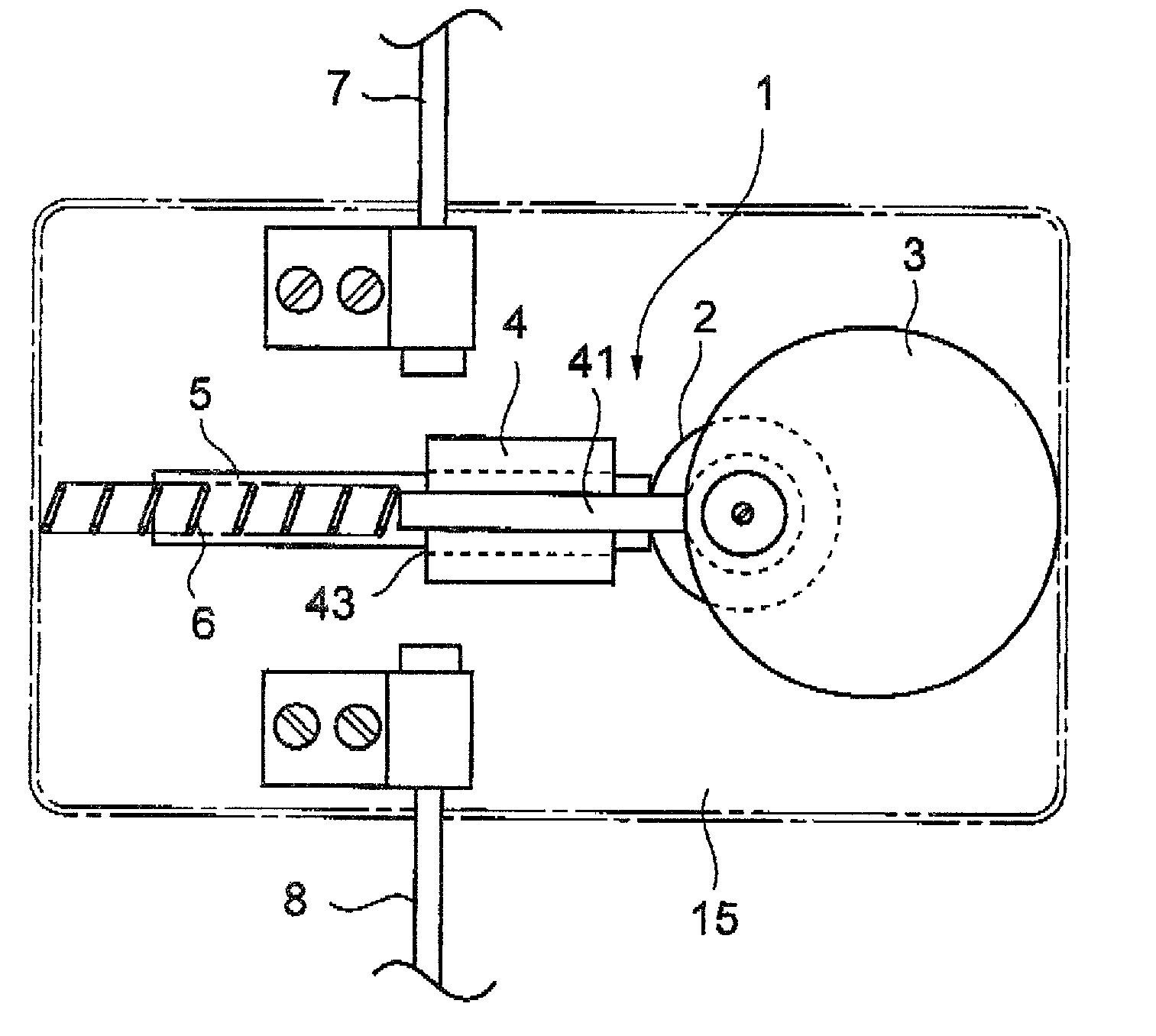
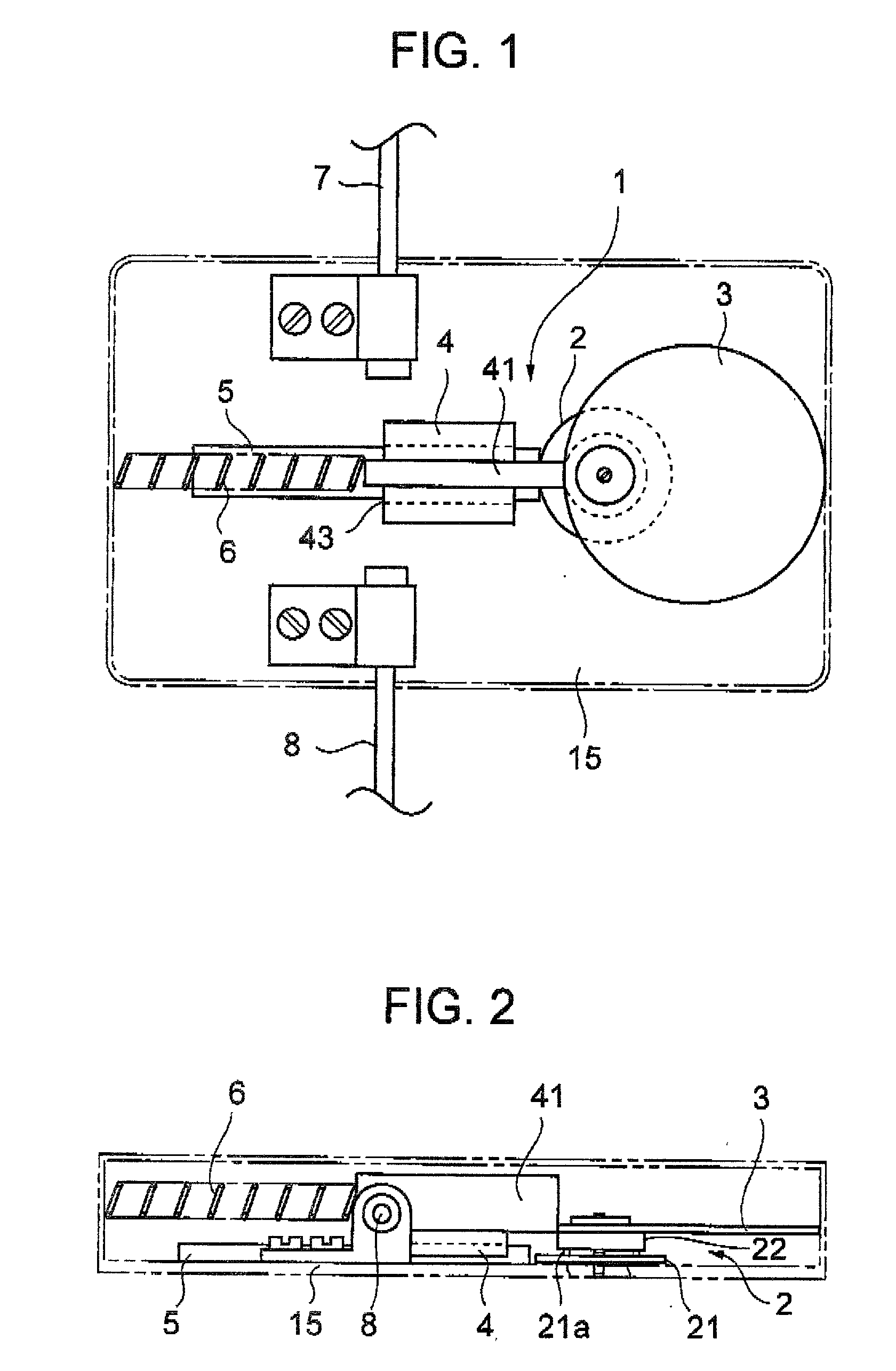
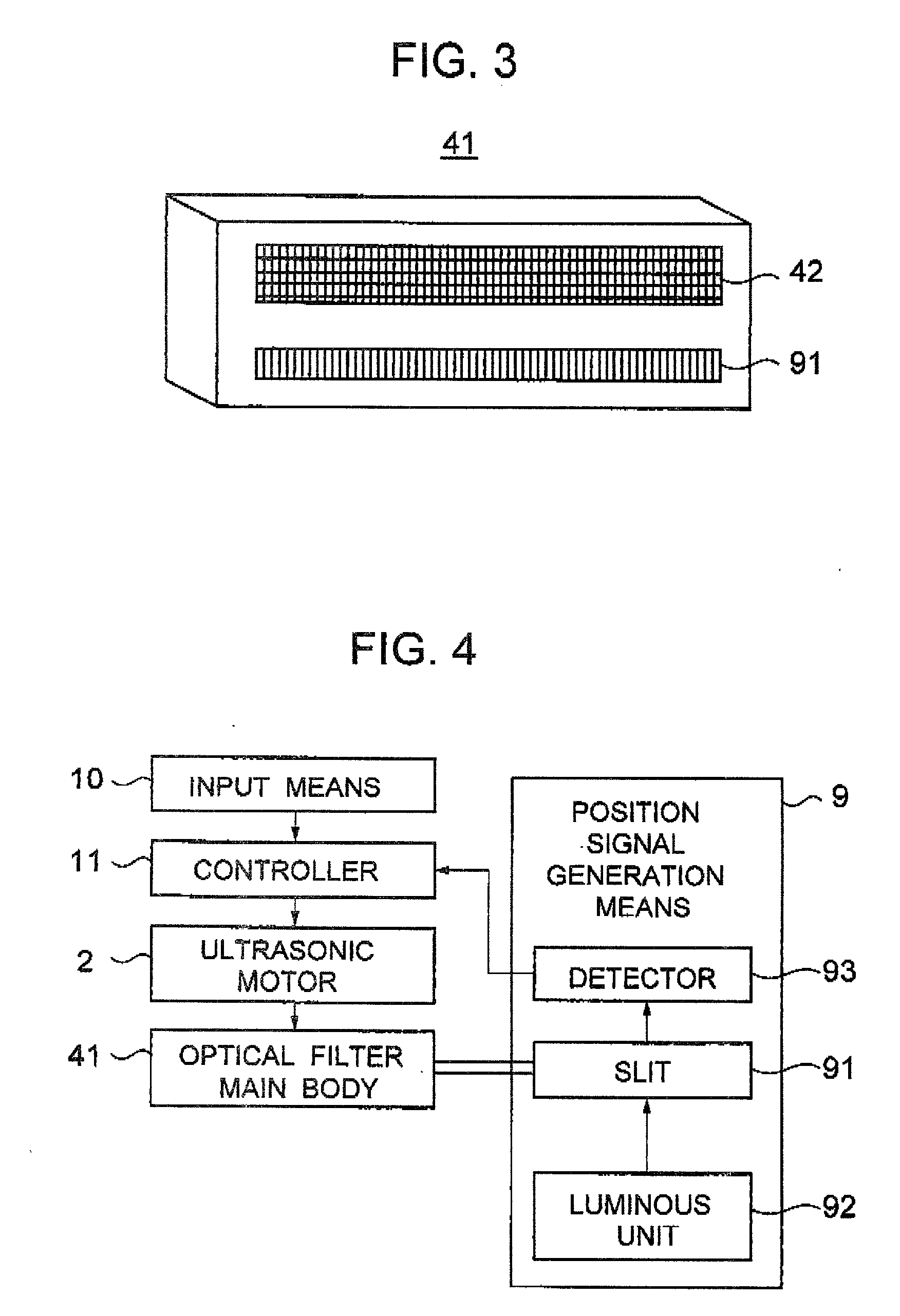
[0033] A description is given of an optical filter moving apparatus 1 that is an example of the apparatus for moving an optical functioning element according to the first embodiment of the invention, with reference to FIG. 1 through FIG. 4.

[0034] As shown in FIG. 1 and FIG. 2, the optical filter moving apparatus 1 is constructed so that a member 4 that moves forward and rearward in one direction by a guiding member 5 and one end of an optical filter main body 41 that is fixed on the moving member 4 and moves in synchronization therewith are brought into contact with the circumferential surface of a disk-shaped eccentric cam 3 that rotates by an ultrasonic motor 2, a coil spring 6 (a pressing means) is brought into contact with the other end of the optical filter main body 41, and the optical filter main body 41 is pressed to the eccentric cam 3 side. That is, as shown in FIG. 3, the optical filter moving apparatus 1 is installed so that a wavelength-varying optical filter 42 of the ...

embodiment 2

[0049] Next, a description is given of an optical filter moving apparatus 100, which is one of the examples of an apparatus for moving an optical functioning element, according to the second embodiment of the invention with reference to FIG. 5 and FIG. 6.

[0050] As shown in FIG. 5 and FIG. 6, the optical filter moving apparatus 100 is constructed roughly equivalently to the construction of the optical filter moving apparatus 1. However, the second embodiment is constructed so that a rotating plate 101 (rotating body) and a shaft 102 are provided instead of the eccentric cam 3, and a holding plate 103 is provided between the optical filter 41 and the moving member 4.

[0051] The rotating plate 101 is a disk concentrically fixed on the rotor 22 of an ultrasonic motor 2.

[0052] The shaft 102 has one end rotatably incorporated in the circumferential edge of the rotating plate 101 and the other end rotatably Incorporated at the end part of the holding pate 103.

[0053] In the optical filter mo...

embodiment 3

[0056] Next, a description is given of an optical filter moving apparatus 110, which is one of the examples of an apparatus for moving an optical functioning element, according to the third embodiment of the invention with reference to FIG. 7 and FIG. 8.

[0057] As shown in FIG. 7 and FIG. 8, the optical filter moving apparatus 110 is constructed roughly equivalently to the construction of the optical filter moving apparatus 1.

[0058] However, the optical filter moving apparatus 110 is not provided with any eccentric cam 3, but it is constructed so that a moving plate 111 is incorporated between the optical filter main body 41 and the moving member 4 so that one end thereof jumps from the moving member 4, a rack pinion 111a is formed at one end side of the moving plate 111, and a gear 112, which rotates by the ultrasonic motor 2, is engaged with the rack pinion.

[0059] In the optical filter moving apparatus 110 thus constructed, as the ultrasonic motor 2 rotates counterclockwise in FIG....


PUM


Abstract

The invention relates to an apparatus for moving an optical functioning element at sufficient accuracy over a long period of use or in a case where the temperature changes, in which a voltage is applied only when moving an optical functioning element, wherein a moving member 4, which moves forward and rearward in one direction by a guiding member 5, and one end of an optical filter main body 41, which is fixed at the moving member 4, are brought into contact with the circumferential surface of a disk-shaped eccentric cam 3 that rotates by an ultrasonic motor 2, and a coil spring 6 is brought into contact with the other end of the optical filter main body 41, whereby pressing the moving member 4 to the eccentric cam 3 side. Also, the apparatus includes a position signal generating means that generates a signal to detect the position of the optical filter main body 41 and a controller that controls the ultrasonic motor 2 in compliance with the signal inputted from the position signal generating means and inputting means.

Description

[0001] 1. Field of the Invention[0002] The present invention relates to an apparatus for moving an optical functioning element, which moves to an appointed position by a piezoelectric actuator.[0003] 2. Description of the Prior Art[0004] It is necessary that a wavelength-varying optical filter, variable attenuator, and optical switch in a wavelength multiplexed optical communication are accurately moved to an appointed position in order to display the performance thereof.[0005] Conventionally, for example, a wavelength-varying optical filter uses a piezoelectric element, or as described in Japanese Patent Publication No. 2874635, they are moved by using a piezoelectric body.[0006] The technology disclosed by Japanese Patent Publication No. 2874635 is as follows;[0007] That is, after a piezoelectric body is returned to an initial state as a preliminary action, a wavelength-varying optical filter is moved by the piezoelectric body, and a drive voltage when an appointed penetration wav...

Claims


Application Information

Patent Timeline
Patent Type & Authority Applications(United States)
IPC IPC(8): G02B26/08G02B5/20G02B7/00H01L41/09H02N2/00
CPCG02B7/005
Inventor SUZUKI, MAKOTOIINO, AKIHIROKASUGA, MASAO
Owner SUZUKI MAKOTO
Why Eureka
Try Eureka