

Automatic transmission case
a transmission case and automatic transmission technology, applied in the direction of gearing control, gear lubrication/cooling, gearing elements, etc., can solve the problems of difficult to achieve the level of quietness expected, difficult to reduce noise further without increasing the rigidity of the transmission case, etc., to achieve sufficient rigidity, improve the rigidity, and improve the rigidity of the casing.
Inactive Publication Date: 2002-02-14
AISIN AW CO LTD
View PDF0 Cites 33 Cited by
- Summary
- Abstract
- Description
- Claims
- Application Information
AI Technical Summary
Benefits of technology
[0013] Furthermore, it is effective if the valve body is fastened by fastening means to the case wall in the vicinity of the front portion and the rear portion of the enclosing wall.
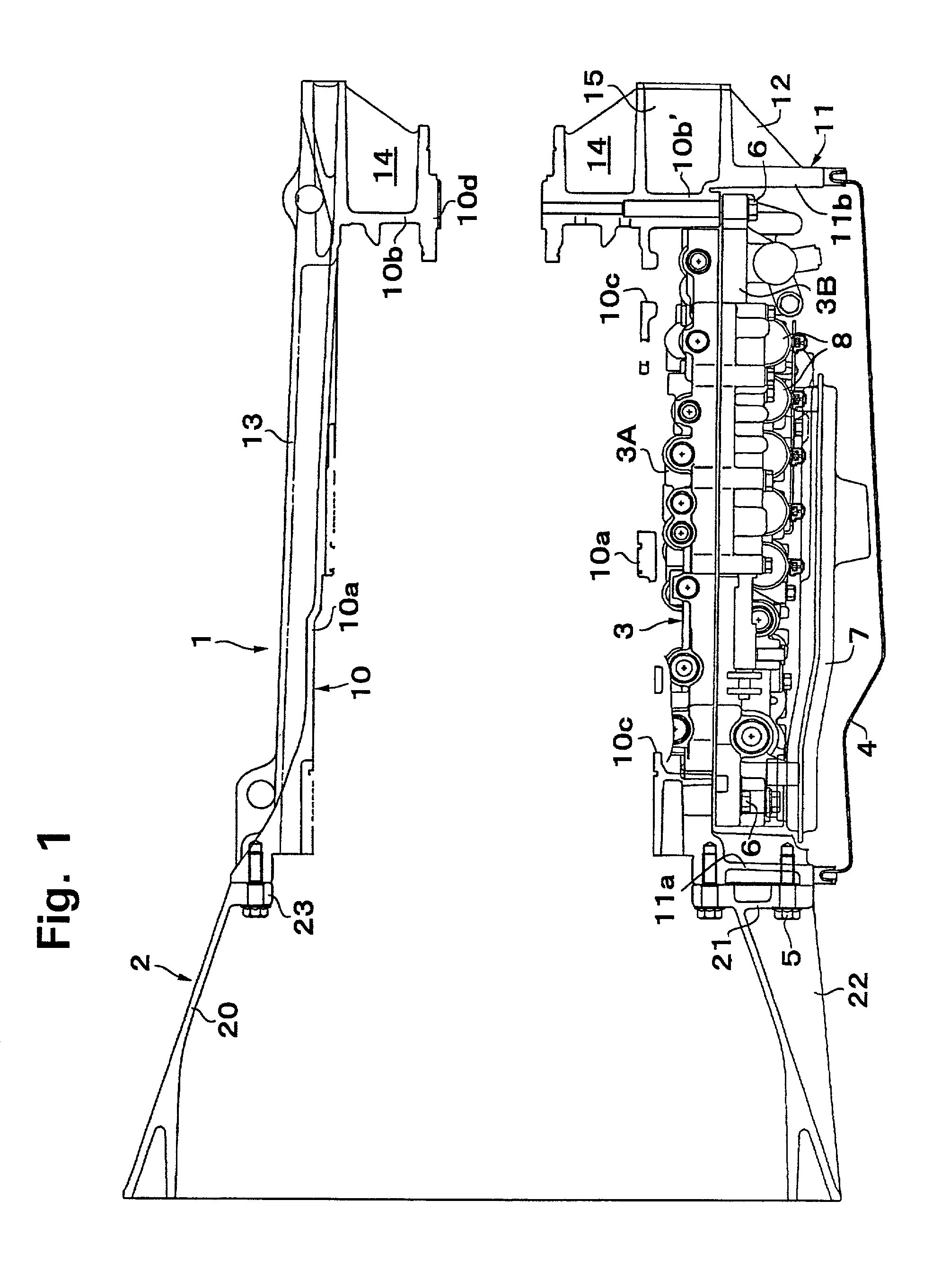
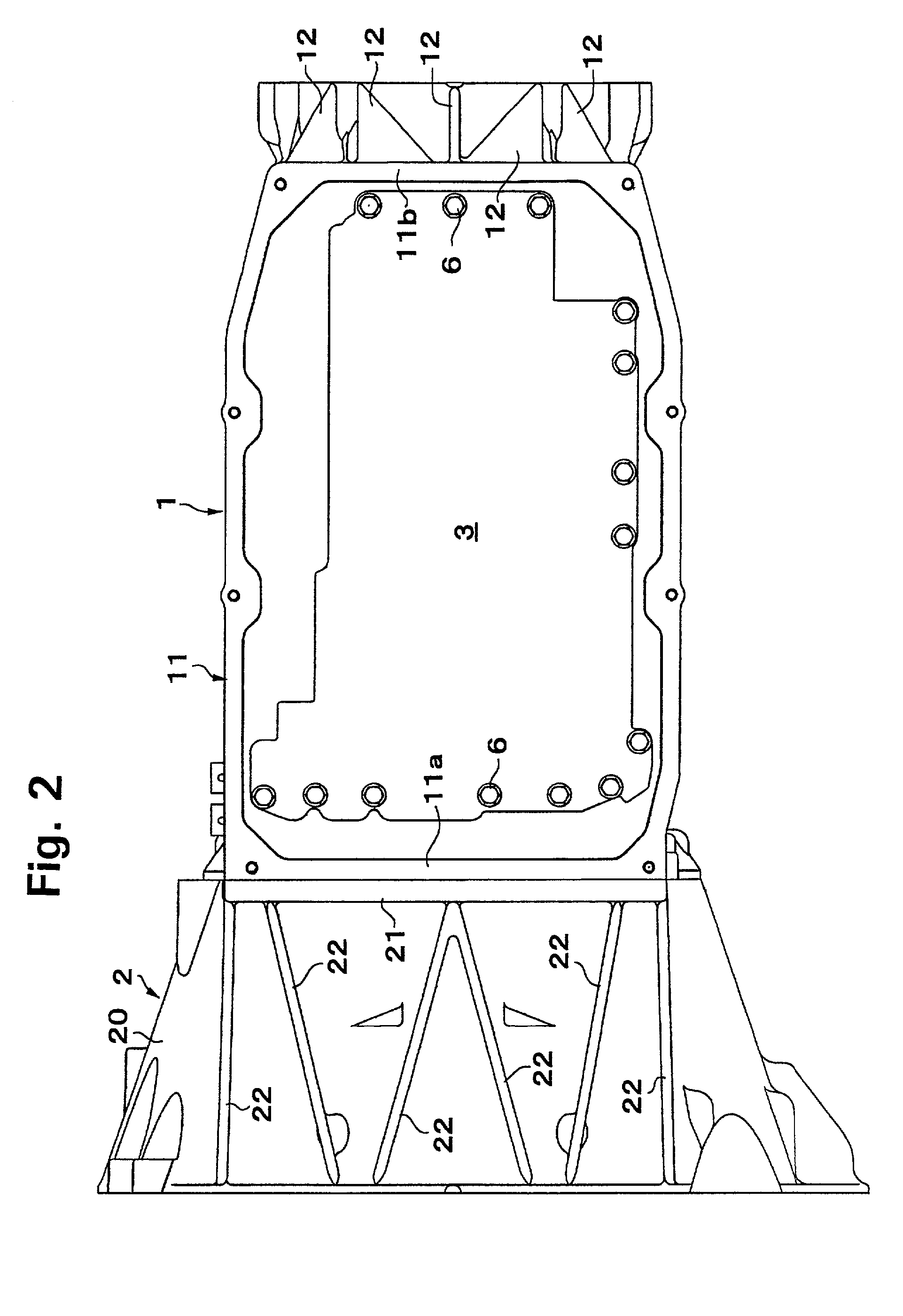
[0041] As described above, because the valve body 3 is completely contained inside the enclosing wall 11, the oil pan 4 covering the opening of the enclosing wall 11 is formed in a shallow dish shape with only the portion that corresponds to the bottom of the intake opening of the strainers 7 fitted to the valve body 3 projecting slightly below the bottommost portion of the enclosing wall 11, in other words, in a shallow dish shape whose bottommost portion protrudes slightly lower than the portion thereof that is placed against the enclosing wall 11 with the seal inserted between the two. By employing this type of structure, it is possible to secure the space for containing the valve body 3 using the shallow oil pan 4 that covers the opening of the containing space and the enclosing wall 11 that is higher than the thickness of the valve body 3, namely, in the embodiment, that is thicker than the valve body lower 3B. As a result, there is no need to lower the position of the oil pan 4 because the enclosing wall 11 has been made to project downwards to secure the required rigidity, and the minimum ground clearance when the automatic transmission is mounted in a vehicle can be secured in the same way as in a conventional structure.
Problems solved by technology
Therefore, it is difficult to secure rigidity in the automatic transmission and when this is mounted in a vehicle and is regarded together with the engine as a vibration system, if the rigidity of this vibration system is low, the vibration system has a resonance point in a comparatively low frequency range near the vibration frequency of the propeller shaft.
Accordingly, if this resonance frequency is a frequency that causes a harsh grating sound to be heard in the audible frequency band, then it is not possible to achieve the level of quietness expected in a running vehicle.
Thus, it is difficult to reduce the noise further without increasing the rigidity of the transmission case to which the transfer is linked.
However, if the case is made thicker, the mass of the case itself is also thereby increased resulting instead in a vibration system with a linking portion having a relatively low rigidity being formed and the desired effect of an improvement in the level of quietness is not obtained.
Method used
View moreImage
Smart ImageViewing Examples

Examples
Embodiment Construction
has been given above based on one embodiment thereof, however, the invention is not limited to the described embodiment, and may be implemented in various configurations within the range described in the claims. In particular, in the described embodiment, the case rear end portion is formed integrally with an adaptor structure for linking with a transfer for a four-wheel drive vehicle, however, when constructing a normal transmission case for an FR vehicle, it is possible, instead of the adaptor structure, to fasten to the case an extension housing in the form of an extremely short cover.
Login to View More PUM
 Abstract
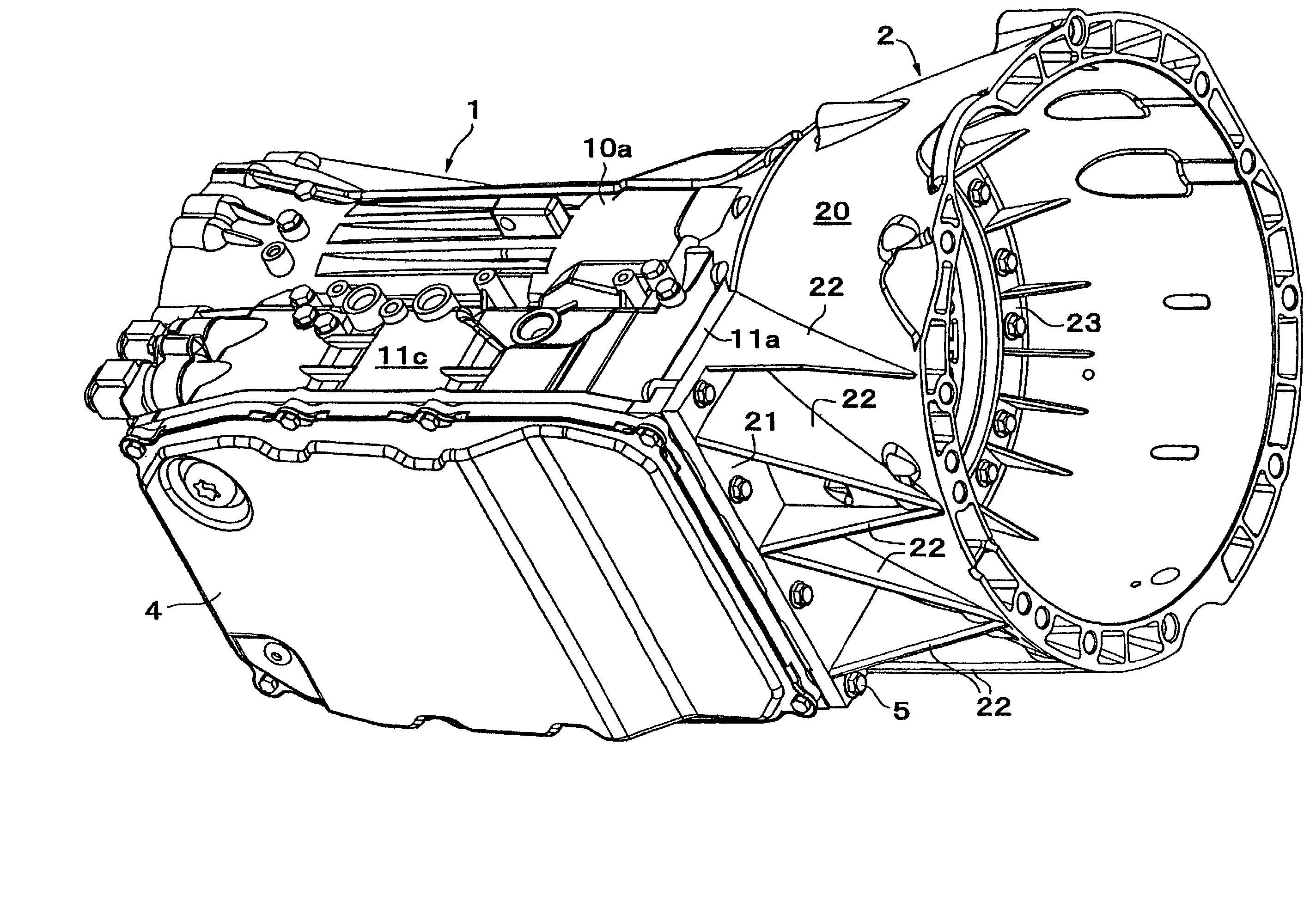
The level of quietness for an automatic transmission case is ensured by preventing vibration by improving the rigidity while suppressing the increase in the mass of a transmission case. In an automatic transmission case in which a valve body is attached to a case wall that covers the transmission mechanism, the rigidity of the automatic transmission case is increased by providing, in the case, an enclosing wall that projects out from the case wall and encloses the periphery of the valve body.
Description
[0001] 1. Field of Invention[0002] The invention relates to a case for an automatic transmission and, in particular, to a vibration resistant structure thereof.[0003] 2. Description of Related Art[0004] A case for an automatic transmission is generally formed from a transmission casing that covers the transmission mechanism, a transmission apparatus housing that is fastened to the front of the casing and that covers a hydraulic power transmission apparatus comprising a torque converter or the like, and an extension housing that is mounted to the rear of the transmission casing. The valve body of the hydraulic control apparatus that controls the hydraulic power transmission apparatus and the transmission mechanism of the automatic transmission is usually mounted on the side of the transmission casing. In an automatic transmission for a front engine rear drive (FR) vehicle, in particular, the valve body is normally fixed to the bottom of the transmission casing and protrudes downwards...
Claims
Login to View More Application Information
Patent Timeline
 Patent Type & AuthorityApplications(United States)
IPC IPC(8): F16H57/02F16H57/025F16H57/028F16H57/029F16H57/03F16H61/00
CPCF16H57/0006F16H57/028F16H57/0452Y10T74/19991F16H2057/02047F16H61/0009Y10T74/2186F16H2057/02043
InventorHAYABUCHI, MASAHIRONISHIDA, MASAAKIKASUYA, SATORUIKE, NOBUKAZU
OwnerAISIN AW CO LTD