
Apparatus for grinding rigid materials

a technology of rigid materials and apparatuses, which is applied in the direction of edge grinding machines, grinding machine components, manufacturing tools, etc., can solve the problems of high rejection rate, time-consuming and inaccurate techniques and methods presently employed, and requiring precise adjustments for the particular size and thickness of glass processed, etc., to achieve rapid and accurate production

Inactive Publication Date: 2002-02-14
BUSHELL LEO +1
View PDF3 Cites 11 Cited by
  • Summary
  • Abstract
  • Description
  • Claims
  • Application Information

AI Technical Summary

Benefits of technology

[0005] Thus, with the problems and disadvantages of prior art methods of the various apparatus known, the present invention was conceived and one of its objectives is to provide edge grinding apparatus for rigid planar materials such as glass which is easy to set up and operate by relatively unskilled personnel.
[0007] It is yet another objective of the present invention to provide a method for grinding rigid materials which is automated for rapid, accurate production.

Problems solved by technology

Certain of the techniques and methods which are presently employed are time consuming and inaccurate or require precise adjustments for the particular size and thickness of the glass processed.
Other disadvantages include extensive labor and handling, often causing high rejection rates.

Method used


Image

  • Apparatus for grinding rigid materials
  • Apparatus for grinding rigid materials
  • Apparatus for grinding rigid materials

Examples


Embodiment Construction

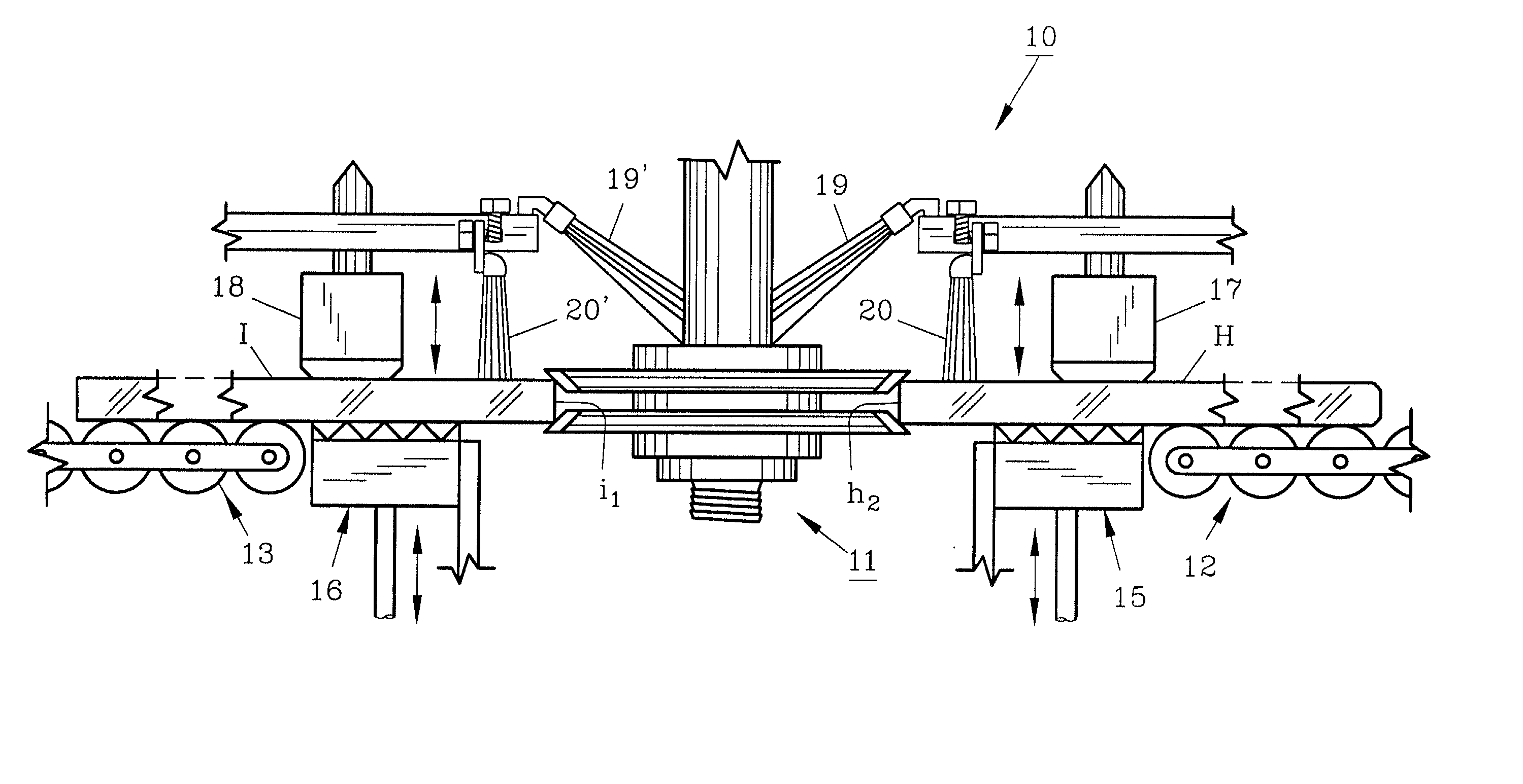
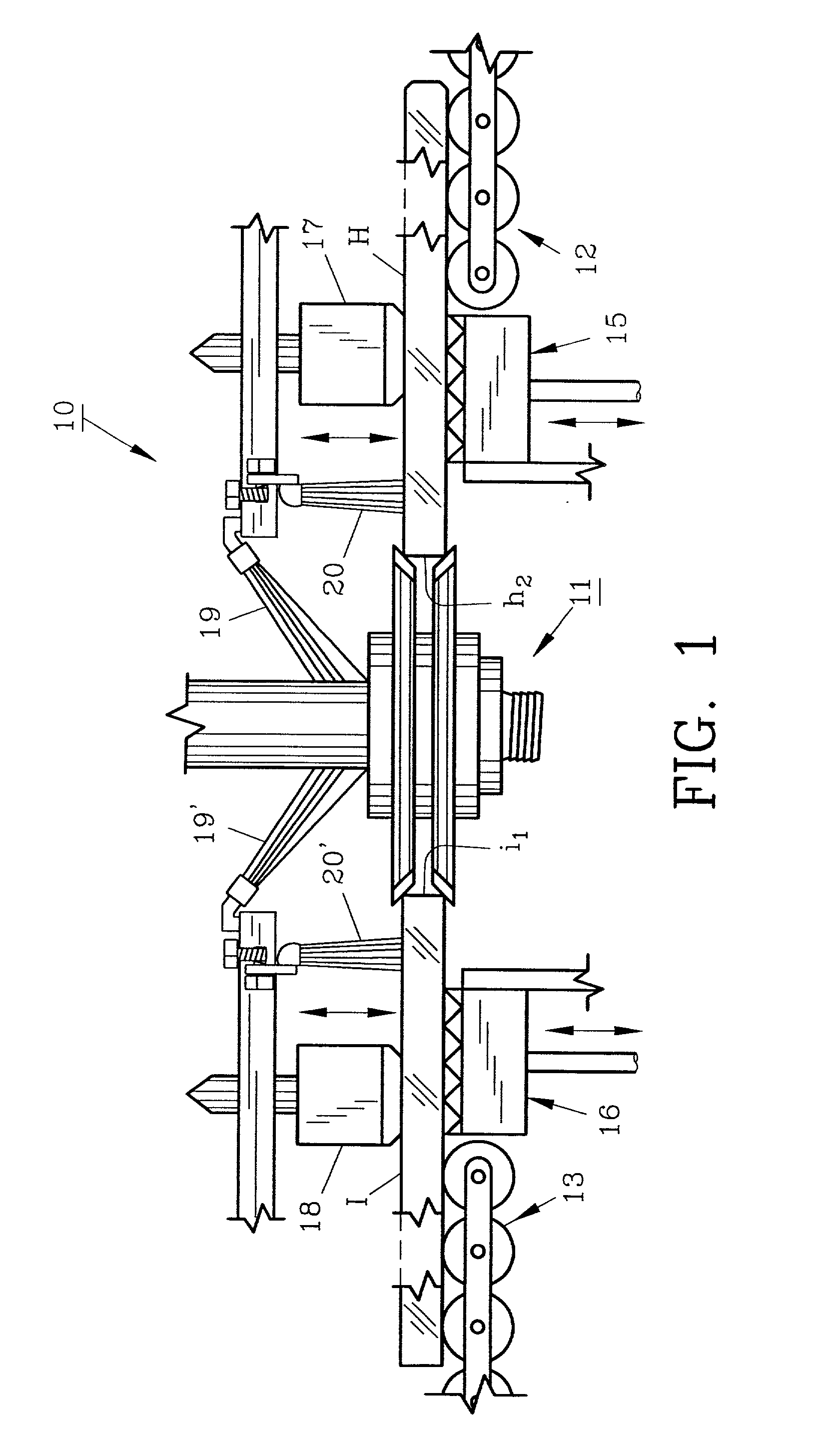
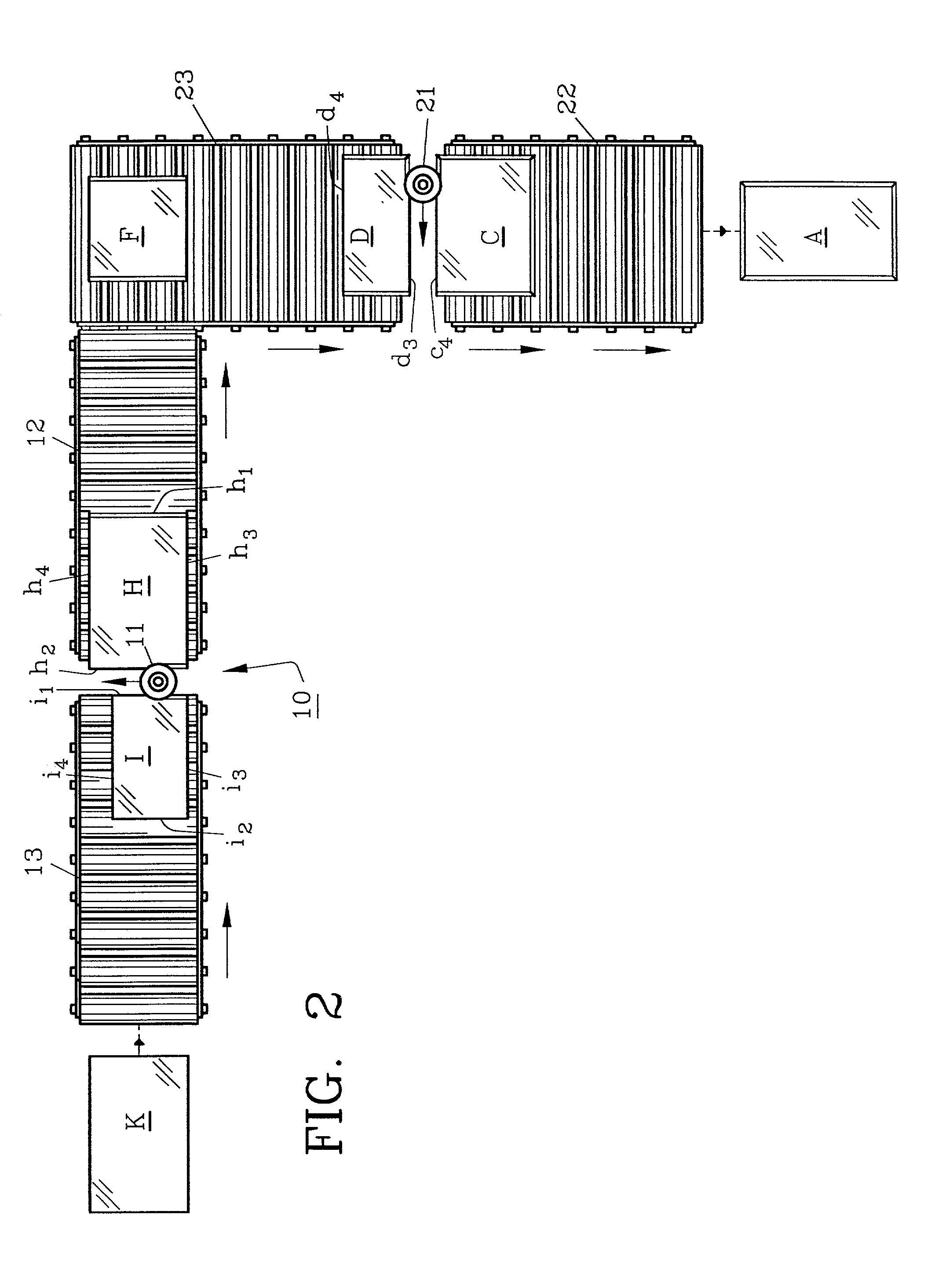
[0022] Turning now to the drawings, preferred apparatus 10 of the invention is shown in FIG. 1 wherein conventional grinding wheel 11 is shown positioned between first rigid planar material H and second rigid planar material I. Planar materials H and I are for example rectangular sheets of plate glass in horizontal alignment (seen in fragmented fashion in FIG. 1 for clarity) although other material such as ceramic tile, stone or other materials may be likewise processed. Grinding wheel 11 is moving along materials H and I simultaneously abrading or grinding the lateral trailing edge h.sub.2 of material H and the lateral leading edge i.sub.1 of material I. Apparatus 10 as shown in FIG. 1 consists of standard abrasive diamond grinding wheel 11, first roller conveyor 12 and second roller conveyor 13. At each end of conveyors 12 and 13 respectively as seen, lower bottom clamps 15 and 16 are positioned to hold rigid materials H and I with upper clamps 17, 18 as conventional in the indust...


PUM

PropertyMeasurementUnit
degree anglesaaaaaaaaaa
sizeaaaaaaaaaa
abrasive sizeaaaaaaaaaa

Abstract

A method and apparatus for processing of planar rigid materials is provided whereby the edges of separate materials can be processed simultaneously, quickly and efficiently. Separate planar materials are moved in position and are clamped in place in horizontal alignment. Thereafter a grinding wheel moves between the opposing edges of the planar materials to abrade the leading edge of one of the materials and the trailing edge of the second opposing material. The process describes abrading both the longitudinal and lateral edges of rectangular shaped materials moved along conveyors, such planar materials being glass, ceramic, stone or the like.

Description

[0001] An apparatus and method for abrading the edges of rigid materials such as glass plates is described whereby opposing edges of different glass plates are simultaneously abraded using a single grinding wheel.DESCRIPTION OF THE PRIOR ART AND OBJECTIVES OF THE INVENTION[0002] Various types of motor driven grinding machines have been available for many years in the glass and other industries whereby sheets or plates of various rigid materials are driven by conveyors and are stopped, clamped and ground (seamed) to remove rough, uneven and jagged edges. The grinding or abrading of the edges is also performed with glass sheets prior to heat tempering where edge uniformity is a requirement. U.S. Pat. Nos. Re. 29,097; 4,633,408; 4,739,586; 4,817,339 and 3,800,477 demonstrate various types of grinding apparatus and methods for processing or seaming the edges of glass with automated equipment.[0003] Tile, stone, ceramics and other planar materials have been processed in the past with one...

Claims


Application Information

Patent Timeline
Patent Type & Authority Applications(United States)
IPC IPC(8): B24B1/00B24B9/10B24B27/00
CPCB24B1/00B24B9/102B24B27/0069
Inventor BUSHELL, SCOTT B.
Owner BUSHELL LEO
Learn More