Contraceptive transcervical fallopian tube occlusion devices and methods

a transcervical, contraceptive technology, applied in the field of contraception, can solve the problems of large variation in the actual shape and dimensions of the fallopian tube, less readily restrained fallopian tube devices, and disruption of normal structure and/or function,

Inactive Publication Date: 2002-02-21
BAYER ESSURE
View PDF0 Cites 125 Cited by
  • Summary
  • Abstract
  • Description
  • Claims
  • Application Information

AI Technical Summary

Benefits of technology

[0017] The intrafallopian devices of the present invention will often comprise a structure having a lumen-traversing region with a helical outer surface. The helical surface is mechanically anchored by a resilient portion of the structure which is biased to form an enlarged secondary shape, preferably forming distal and proximal anchoring loops. The anchoring loops help prevent the helical outer surface from rotating out of position, and also directly deter axial motion within the fallopian tube. In alternative embodiments, anchoring may be provided by a straight coil which is resiliently deflected by the axial curvature of the tortuous fallopian tube, and a radially expandable braid, malecott, or some other tubular structure may help affix the device within the fallopian tube.
[0018] The use of copper in the intrafallopian device of the present invention improves its efficacy as a contraceptive method. Devices formed from plastically deformable materials, however, are less readily restrained in the fallopian tube. Apparently, the large variation in the actual shape and dimensions of fallopian tubes does not provide reliable anchoring for a preformed deformable intrafallopian device. The intrafallopian device of the present invention therefore often comprises a resilient structure, usually a metallic coil, which includes a copper alloy or plating, ideally comprising an alloy including at least 75% copper. The coil material typically includes beryllium, zinc, stainless steel, platinum, a shape memory alloy, such as Nitinol.RTM., or the like. Preferably, the coil is composed of an alloy of beryllium and copper.

Problems solved by technology

Devices formed from plastically deformable materials, however, are less readily restrained in the fallopian tube.
Apparently, the large variation in the actual shape and dimensions of fallopian tubes does not provide reliable anchoring for a preformed deformable intrafallopian device.
Although the present device will generally result in occlusion, it need not completely occlude the fallopian tube to prevent the meeting of the sperm and ovum.
Hence, contraception can be provided by disrupting the normal architecture and / or function of the fallopian tube, despite the presence of an open lumen.
As used herein, functional occlusion means that the device, when implanted in the fallopian tube, disrupts the normal architecture and / or functioning of the fallopian tube so as to inhibit fertilization and / or conception.
Such tubular devices will often effect contraception by disrupting the architecture and / or transport mechanisms of the tubal tissues, rather than relying entirely on total blockage of the tube.

Method used


Image

  • Contraceptive transcervical fallopian tube occlusion devices and methods
  • Contraceptive transcervical fallopian tube occlusion devices and methods
  • Contraceptive transcervical fallopian tube occlusion devices and methods

Examples


Embodiment Construction

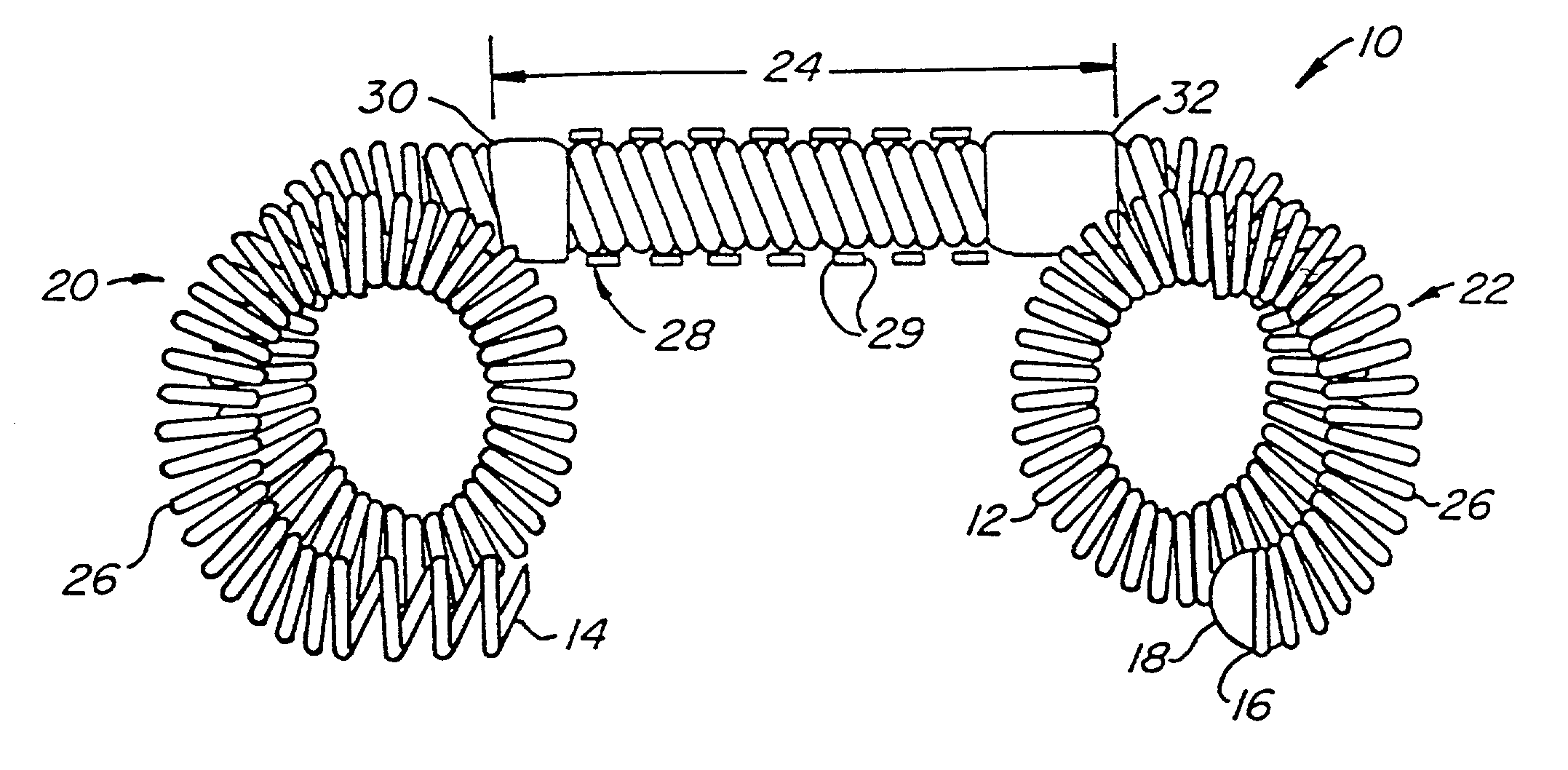
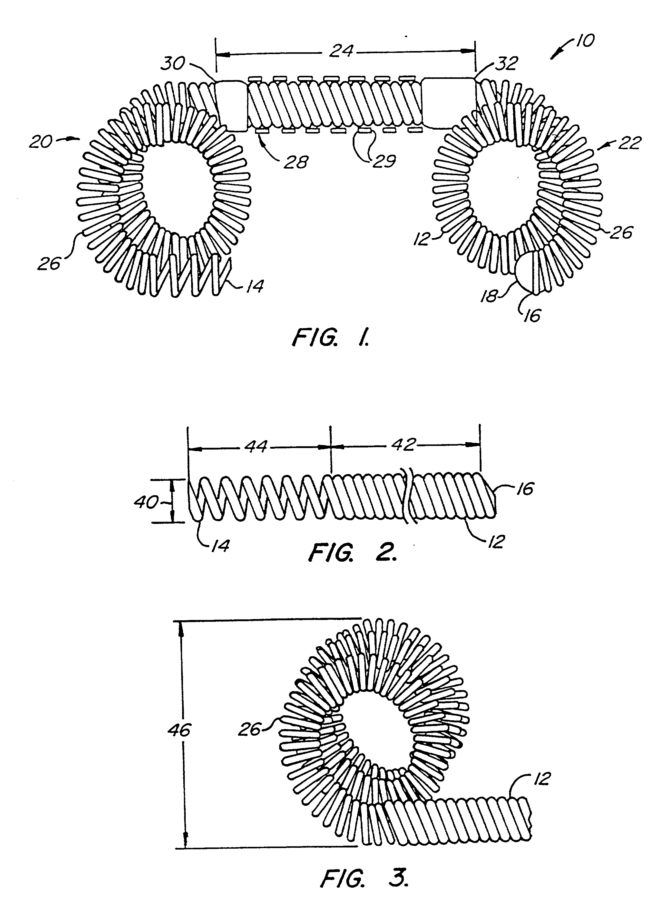
[0061] The present invention encompasses a contraceptive intrafallopian device which can alternatively be used as both a permanent and a reversible means of contraception. The present contraceptive methods and devices minimize the danger of non-use which has limited the efficacy of prior art contraceptive techniques. Moreover, the location of the present devices within the fallopian tubes provides a reduced risk of the infectious complications, increased bleeding, and pelvic pain associated with intrauterine devices (IUDs). The location and the novel shape of the present intrafallopian device provides significant advantages over IUDs, which have been found to be susceptible to unplanned expulsion and removal due to excessive pain and bleeding. The present invention takes advantage of the increase in effectiveness associated with copper IUDs, providing a resilient structure including copper which may be transcervically positioned without the need for surgery.

[0062] Although the prese...


PUM

PropertyMeasurementUnit
lengthaaaaaaaaaa
outer diameteraaaaaaaaaa
lengthaaaaaaaaaa

Abstract

The invention provides intrafallopian devices and non-surgical methods for their placement to prevent conception. The efficacy of the device is enhanced by forming the structure at least in part from copper or a copper alloy. The device is anchored within the fallopian tube by a lumen-traversing region of the resilient structure which has a helical outer surface, together with a portion of the resilient structure which is biased to form a bent secondary shape, the secondary shape having a larger cross-section than the fallopian tube. The resilient structure is restrained in a straight configuration and transcervically inserted within the fallopian tube, where it is released. Optionally, permanent sterilization is effected by passing a current through the resilient structure to the tubal walls.

Description

CROSS-REFERENCES TO RELATED APPLICATIONS[0001] This application is a continuation of U.S. patent application Ser. No. 09 / 592,123 filed on Jun. 12, 2000, which is a continuation of U.S. patent application Ser. No. 09 / 324,078 filed on Jun. 1, 1999, which is a continuation-in-part of International Application No. PCT / US98 / 20031, filed Sep. 23, 1998, which is a continuation-in-part of U.S. patent application Ser. No. 09 / 093,835, filed Jun. 8, 1998, which claims the benefit of priority from U.S. Provisional Application No. 60 / 059,861, filed Sep. 24, 1997, and is also a continuation-in-part of U.S. patent application Ser. No. 08 / 475,252 filed Jun. 7, 1995, and a continuation-in-part of U.S. patent application Ser. No. 08 / 474,779 filed Jun. 7, 1995, now U.S. Pat. No. 6,176,240, the full disclosures of which are incorporated herein by reference.[0002] 1. Field of the Invention[0003] The present invention relates generally to contraception, and more particularly to intrafallopian contracepti...

Claims


Application Information

Patent Timeline
Patent Type & Authority Applications(United States)
IPC IPC(8): A61B17/12A61F2/00A61F6/06A61F6/18A61F6/22
CPCA61B17/12022Y10T29/49826A61B17/1215A61B2017/12063A61B2017/12095A61F2/0077A61F6/18A61F6/22A61F6/225A61B17/12099A61B18/082A61B19/5244A61B2017/00867A61B2017/12059A61B2018/046A61B2019/5238A61B2019/5276A61B2017/12077A61B17/12145A61B34/20A61B2090/376A61B2090/378
Inventor NIKOLCHEV, JULIAN N.TON, DAI T.KHERA, ASHISHGURSKIS, DONNELL W.BACICH, STEVEN
Owner BAYER ESSURE
Why Eureka
Try Eureka