Thermosensitive printer

a printer and thermosensor technology, applied in the field of thermosensors, can solve the problem of inability to obtain adequate graininess

Inactive Publication Date: 2002-02-21
FUJIFILM HLDG CORP +1
View PDF0 Cites 5 Cited by
  • Summary
  • Abstract
  • Description
  • Claims
  • Application Information

AI Technical Summary

Problems solved by technology

In this type of printer, adequate graininess cannot be obtained by displacing the center of

Method used


Image

  • Thermosensitive printer
  • Thermosensitive printer
  • Thermosensitive printer

Examples


Embodiment Construction

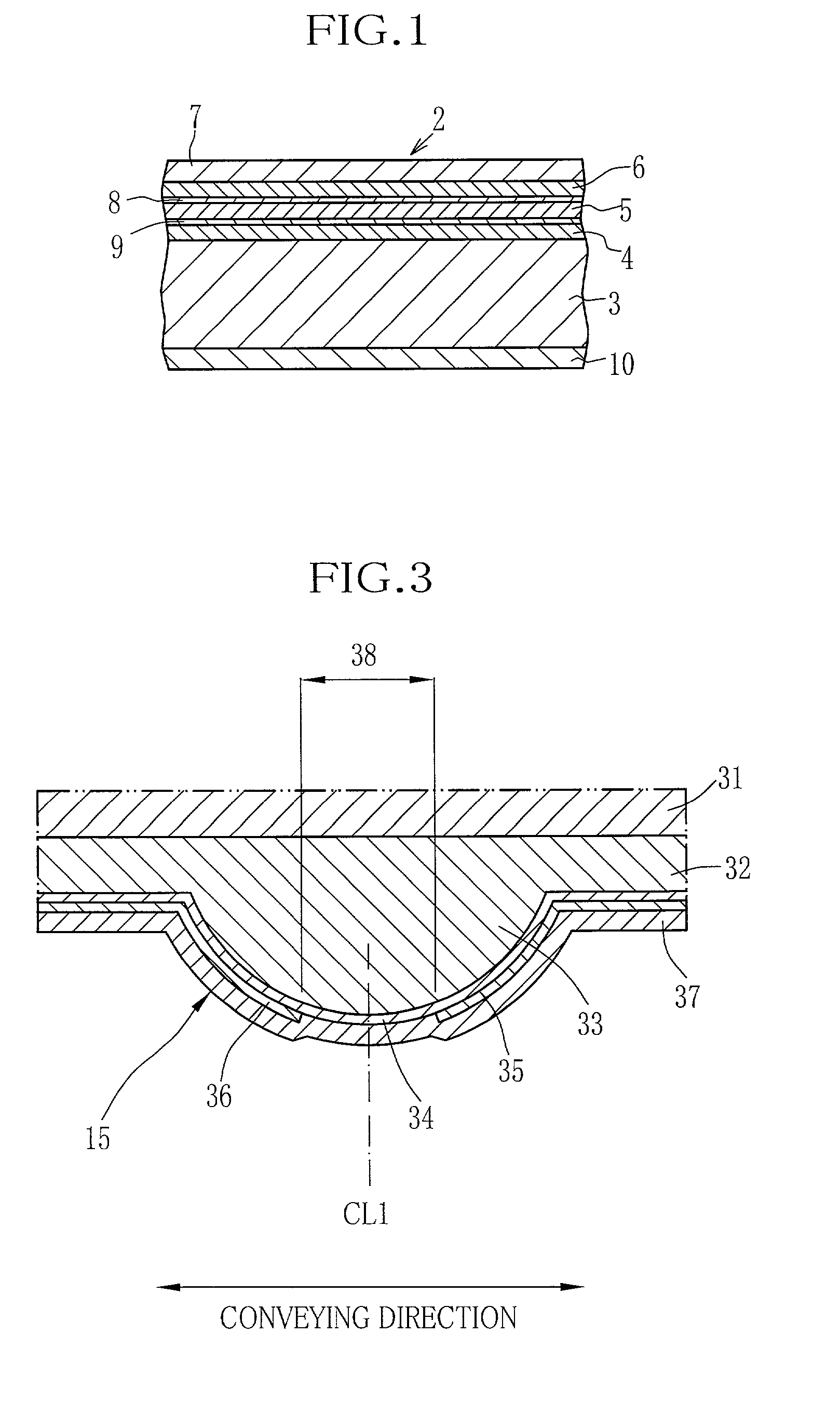
[0023] As shown in FIG. 1, a thermosensitive color recording material 2 has a thermosensitive cyan coloring layer 4, a thermosensitive magenta coloring layer 5, a thermosensitive yellow coloring layer 6 and a transparent protection layer 7 formed atop another on one side of a base material 3. The uppermost yellow coloring layer 6 has the highest thermal sensitivity and is fixed or loses its coloring ability when exposed to near-ultraviolet rays of 420 nm. The magenta coloring layer 7 has a lower thermal sensitivity and is fixed when exposed to ultraviolet rays of 365 nm. The lowermost cyan coloring layer 8 has the lowest thermal sensitivity. The protection layer 7 is made of a resin whose main component is PVA (polyvinyl-alcohol), and protects the coloring layers from scratches and stains. Intermediate layers 8 and 9 are provided between the three coloring layers, for adjusting thermal sensitivities of the coloring layers. Designated by 10 is a backing layer.

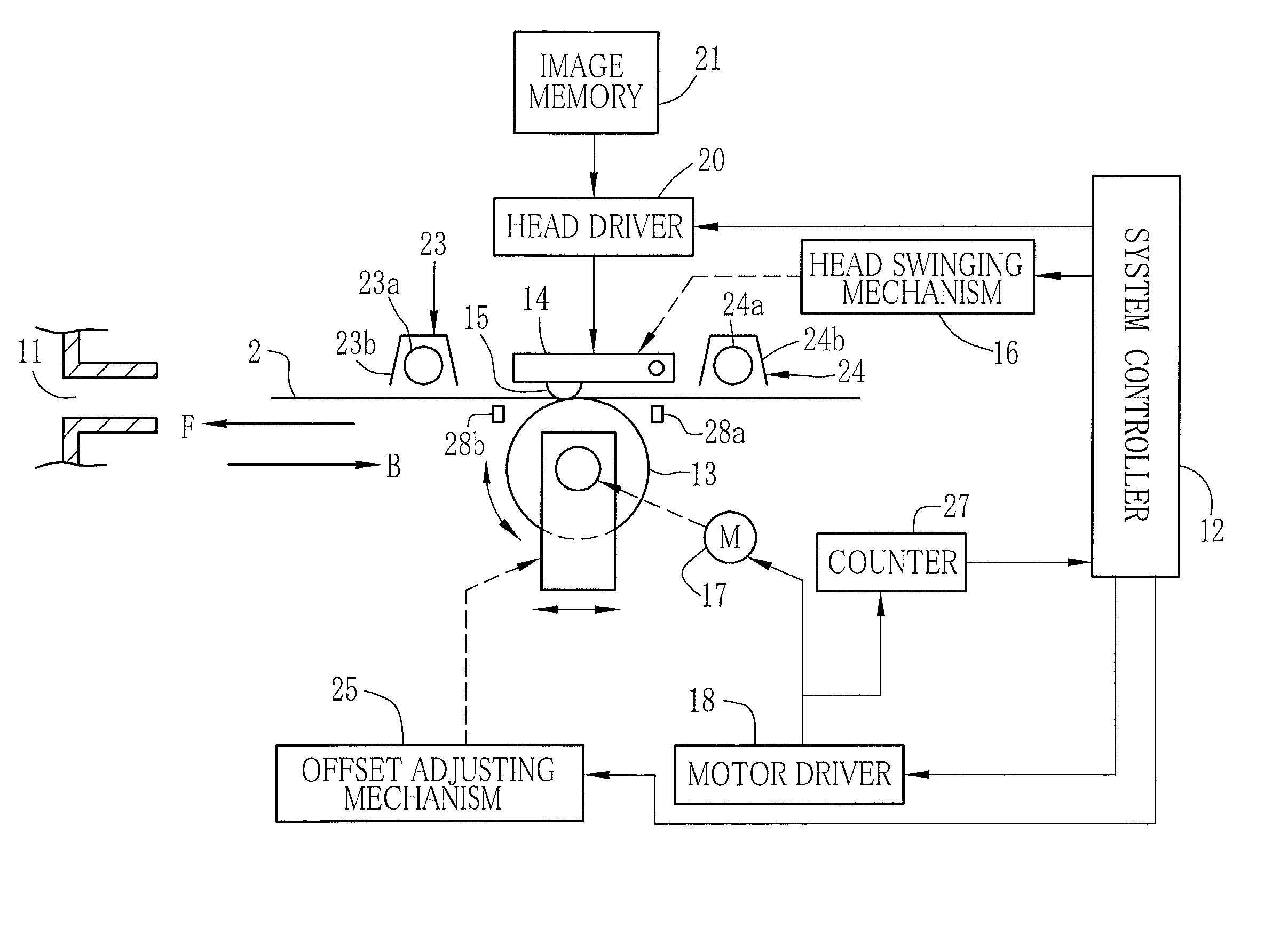
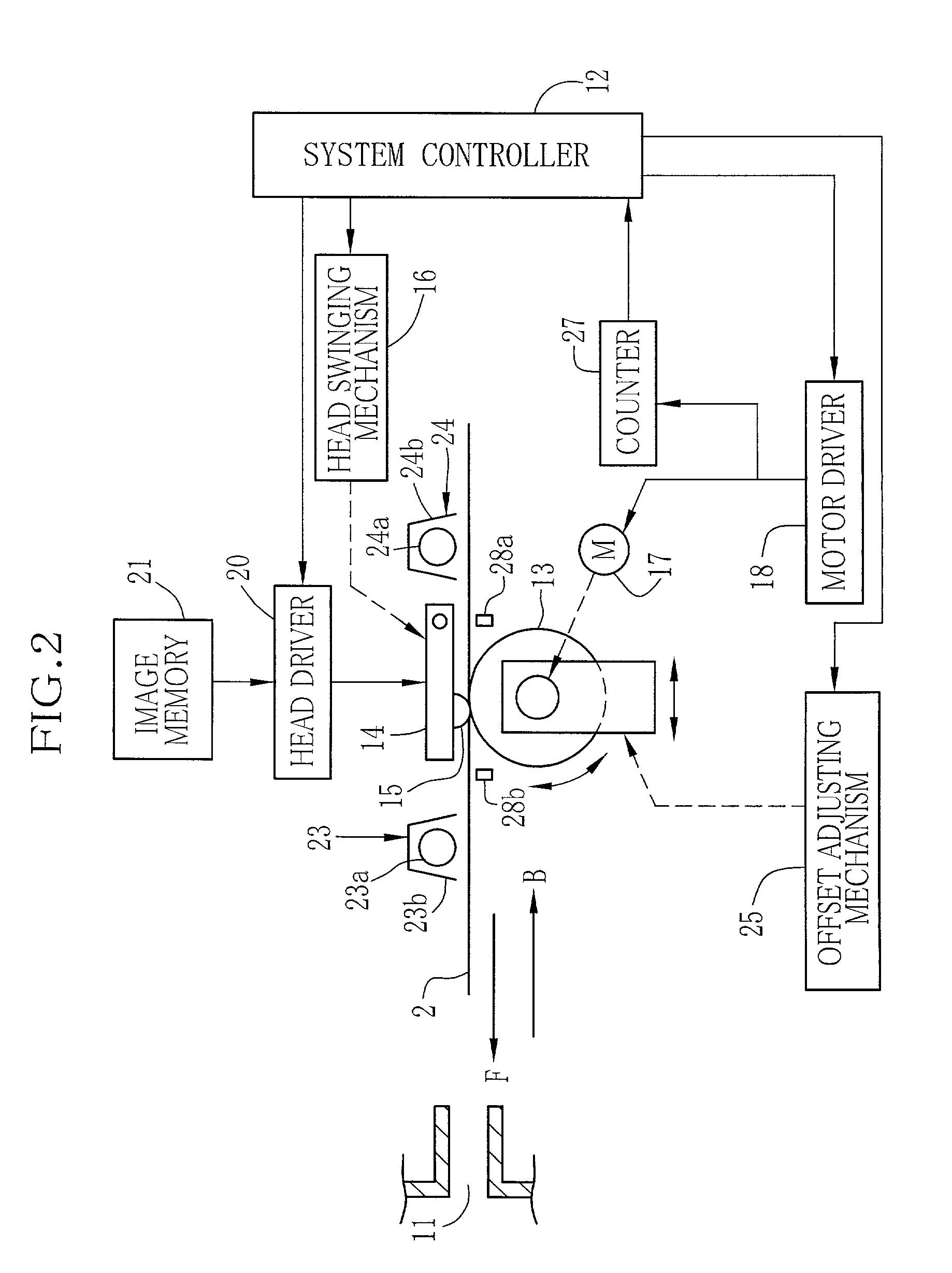
[0024] FIG. 2 shows an e...


PUM


Abstract

To record an image on a thermosensitive color recording material, a heating element array (15) of a thermal head (14) is pressed onto an obverse side of the thermosensitive color recording material (2) while a platen roller (13) supports the color recording material from its back side. The thermosensitive color recording material is conveyed first in a forward direction for recording a yellow frame, next in a backward direction for recording a magenta frame, and then again in the forward direction for recording a cyan frame. A rotary shaft of the platen roller is mounted to bearing members (40) that are caused by a pair of piezoelectric actuators (44) to slide back and forth along conveying directions of the thermosensitive color recording material, thereby to displace a rotary center of the platen roller upstream from a center of the heating element in either conveying direction of the thermosensitive color recording material.

Description

[0001] 1. Field of the Invention[0002] The present invention relates to a thermosensitive printer, and more particularly to a thermosensitive color printer where a full-color image is recorded on a thermosensitive color recording material in a three-color frame sequential fashion while the thermosensitive color recording material is being moved back and forth relative to a thermal head.[0003] 2. Background Arts[0004] The thermosensitive color recording material used in the thermosensitive color printer has thermosensitive coloring layers for cyan, magenta and yellow formed atop another on one side of a base material, and a transparent protection layer is formed on an uppermost coloring layer. Hereinafter, the thermosensitive color recording material will be called simply the color recording material. As the color recording material moves relative to the thermal head that is pressed on the top side of the color recording material, the thermal head heats the color recording material s...

Claims


Application Information

Patent Timeline
IPC IPC(8): B41J2/315B41J2/32B41J2/335
CPCB41J2/315B41J2/33525B41J2/33545
Inventor NISHIMURA, TOMOYOSHI
Owner FUJIFILM HLDG CORP
Why Eureka
Try Eureka