Heating furnace

a heating furnace and heating element technology, applied in the field of heating furnaces, can solve the problems of loosened or broken bolts, contaminated inside of the furnace and a heated object, and a large amount of heat, so as to reduce the bolt-fastening force, improve the design effect, and facilitate the heating

Active Publication Date: 2018-01-11
SHIN ETSU CHEM IND CO LTD
View PDF0 Cites 2 Cited by
  • Summary
  • Abstract
  • Description
  • Claims
  • Application Information

AI Technical Summary

Benefits of technology

[0011]By satisfying the above-described relation, even if rising and falling the temperature repeatedly in use environment, the bolt is not likely to be broken or loosened, whereby the contact condition between the heater and the electrode can be maintained favorably over a long period of time.
[0012]In addition, by selecting a material to satisfy the relation of α0>αH, it becomes easier to design the heating furnace that satisfies the above-described relational expression.
[0013]Further, by selecting isotropic graphite, which has a larger linear expansion coefficient than that of a C / C composite or the like, as the material for the bolt, it becomes easier to design the heating furnace that satisfies the relation of α0>αH.
[0014]Moreover, by designing the heating furnace to satisfy the relation of |L0·α0−(TH·αH+TB·αB+TE·αE)|·ΔT≦0.06(TB+TE), decrease of the bolt-fastening force caused by the rising and falling of the temperature can be suppressed, whereby the contact condition between the heater and the electrode can be maintained favorably over a long period of time.

Problems solved by technology

In some cases, as rising and falling the temperature of the heater repeatedly, the bolt is loosened or broken.
If the bolt is loosened, the contact between the heater and the electrode becomes poor so as to cause a voltage to fluctuate, and if the bolt is further loosened, a spark may be generated between the heater and the electrode so as to generate black smoke, thereby contaminating an inside of the furnace and a heated object considerably.
Further, if the bolt is broken, electricity is not conducted at all, or a spark is generated depending on its condition, thereby causing the same result as that in the case of loosening the bolt.
In the case where isotropic graphite that is the same material as that for the heater is used for the bolt, the bolt is likely to be broken.
Whereas, in the case of using a bolt made of a C / C composite having high strength to prevent the breaking, the bolt is unlikely to be broken, but is likely to be loosened as rising and falling the temperature repeatedly.

Method used


Image

  • Heating furnace
  • Heating furnace
  • Heating furnace

Examples


Embodiment Construction

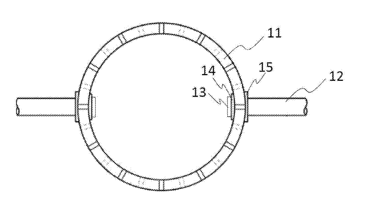
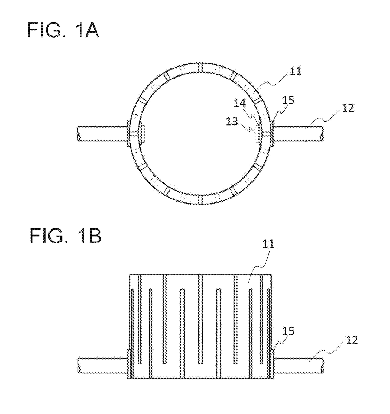
[0019]FIG. 1A and FIG. 1B are schematic views illustrating a structural example of a heating furnace of the present invention. FIG. 1A is a plan view; and FIG. 1B is a front view. The heating furnace of the present invention is provided with a heater 11, an electrode rod 12, a bolt 13, a first washer 14 and a second washer 15.

[0020]The heater 11 is a slit heater having a cylindrical shape and slits that are cut from an upper end and a lower end alternately. As a material for the heater 11, a graphite brittle material such as isotropic graphite and a C / C composite is used to obtain a high temperature of 1000° C. to 2500° C. in an inert gas atmosphere. Incidentally, FIG. 1A and FIG. 1B show an example of connecting the electrode rod directly to a side face of the slit heater, but the present invention can be applied to other types of heaters such as a slit heater having a heater terminal extended upward or downward therefrom and a plate heater in a flat shape.

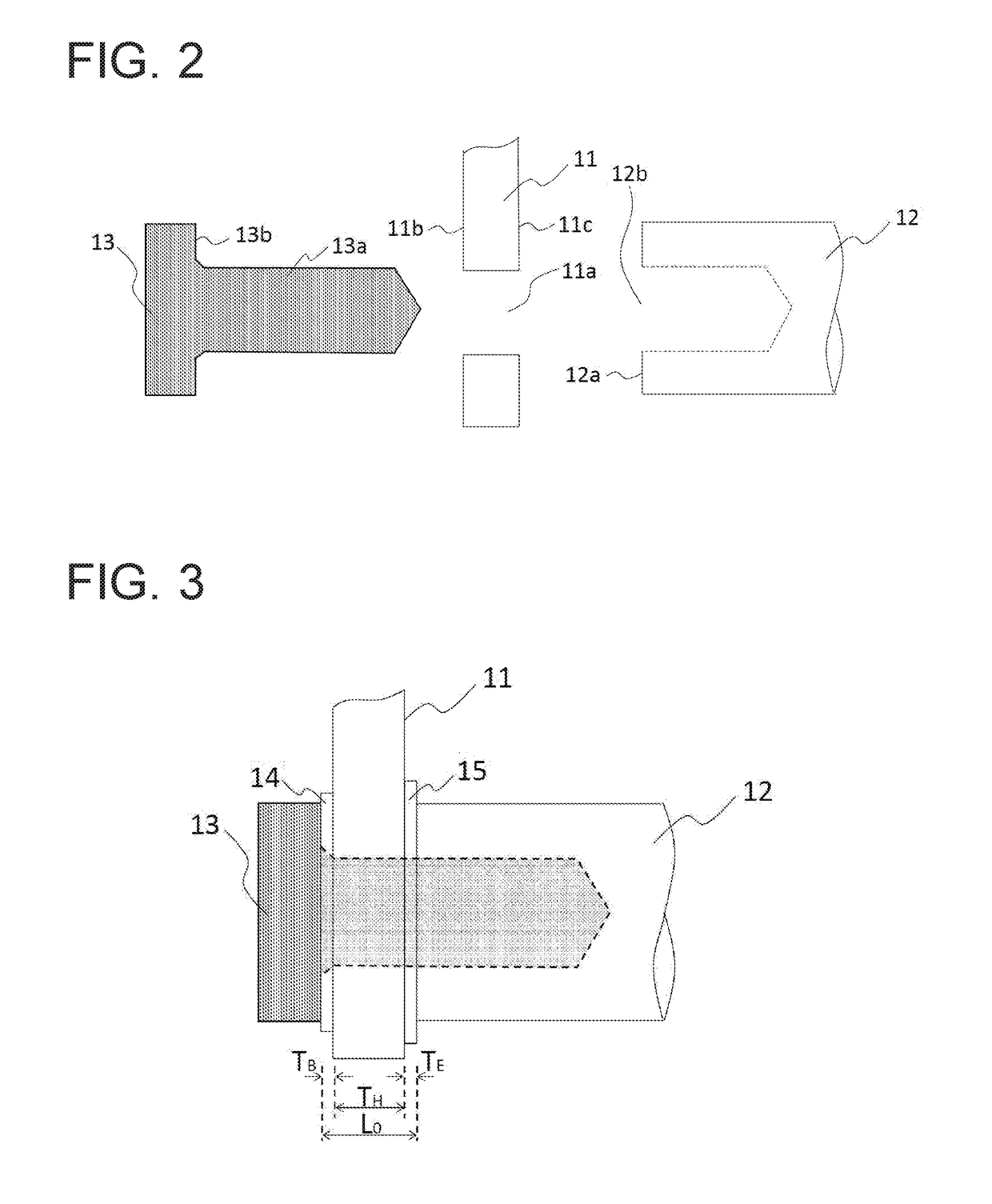
[0021]One end of the elec...


PUM

PropertyMeasurementUnit
temperatureaaaaaaaaaa
brittleaaaaaaaaaa

Abstract

A heating furnace includes a bolt inserted through an insertion hole in a part of a heater and further inserted into a hole on a tip surface of an electrode rod. A first washer is between a bearing surface of the bolt and one face of the heater. A second washer is between another face of the heater and the tip surface. The relation of: |L0·α0−(TH·αH+TB·αB+TE·αE)|·ΔT≦0.15(TB+TE) is satisfied, where L0 is an interval between the bearing surface and the tip surface, α0 is a linear expansion coefficient (LEC) of the bolt, TH, TB and TE are thicknesses of the part, first and second washers and αH, αB and αE are their LECs, respectively, and ΔT is a temperature increment quantity of a part where the heater and the electrode rod are fastened by the bolt.

Description

CROSS-REFERENCE TO RELATED APPLICATION[0001]This non-provisional application claims priority under 35 U.S.C. §119(a) from Japanese Patent Application No. 2016-137085, filed on Jul. 11, 2016 and Japanese Patent Application No. 2017-098645, filed on May 18, 2017, the entire contents of which are incorporated herein by reference.BACKGROUNDTechnical Field[0002]The present invention relates to a heating furnace which is used for heating in steps for manufacturing and processing synthetic quartz glass, a step for drawing an optical fiber and the like, and particularly relates to a heating furnace in which a heater and an electrode are bound with each other by a bolt.Related Art[0003]A carbon heater, which is broadly used in steps for manufacturing and processing synthetic quartz glass, a step for drawing an optical fiber and the like, is made of a graphite material such as isotropic graphite and a C / C composite, and can obtain a temperature of about 1000° C. to about 2500° C. in an inert ...

Claims


Application Information

Patent Timeline
Patent Type & Authority Applications(United States)
IPC IPC(8): H05B3/14C21D9/00H05B3/03H05B3/40
CPCH05B3/145H05B3/40H05B3/03C21D9/0006H05B3/64H05B3/66H05B2203/016
Inventor OTOSAKA, TETSUYA
Owner SHIN ETSU CHEM IND CO LTD
Why Eureka
Try Eureka